Two-freedom-degree parallel-connection rotation mechanism with spherical surface pure-rolling property

A technology of rotating mechanism and degree of freedom, applied in the direction of non-electric variable control, instrument, position/direction control, etc., can solve the problems of difficult popularization and application, few new configurations, unfavorable motion space planning and design, etc., to achieve easy manufacturing, strong The effect of bearing capacity and simple structure

Inactive Publication Date: 2013-07-24
BEIHANG UNIV
View PDF9 Cites 53 Cited by
  • Summary
  • Abstract
  • Description
  • Claims
  • Application Information

AI Technical Summary

Problems solved by technology

At present, there are no relevant research results of such institutions in China; although good results have been achieved in the research and application process of such institutions abroad, there are few new configurations, which are not easy to popularize and apply; sports platforms in existing institutions Both the base and the base are flat, which is not conducive to the planning and design of the sports space

Method used


Image

  • Two-freedom-degree parallel-connection rotation mechanism with spherical surface pure-rolling property
  • Two-freedom-degree parallel-connection rotation mechanism with spherical surface pure-rolling property
  • Two-freedom-degree parallel-connection rotation mechanism with spherical surface pure-rolling property

Examples


Embodiment 1

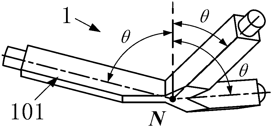
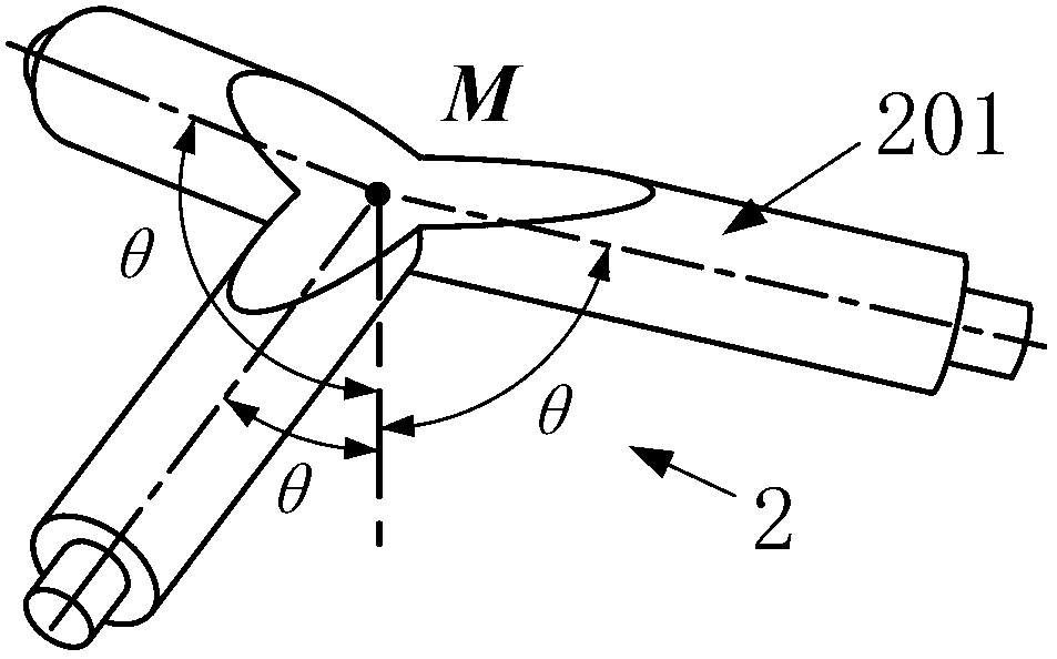
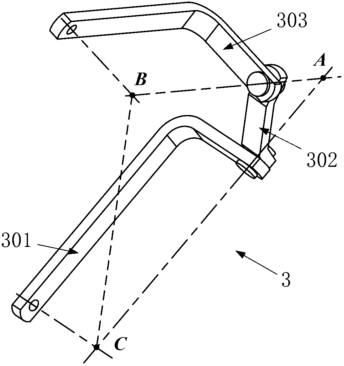
[0062] Such as Figure 5 As shown, the two-degree-of-freedom parallel rotation mechanism includes a fixed base 1, a moving platform 2, and a configuration A kinematic branch chain 3; both the fixed base 1 and the moving platform 2 have three symmetrically distributed rotating pair connection axes; The positioning surface in 1 is set opposite to the installation surface in motion platform 2; the rotating pair connection hole of the upper link 303 in each configuration A motion branch chain 3 is connected with the rotating pair connecting shaft on the moving platform 2 to form a rotating pair; The rotating pair connecting hole of the connecting rod 301 is connected with the rotating pair connecting shaft on the fixed base 1 to form a rotating pair.

Embodiment 2

[0064] Such as Image 6 As shown, it includes a fixed base 1, a moving platform 2, and three configuration A kinematic branch chains 3; both the fixed base 1 and the moving platform 2 contain three symmetrically distributed rotating pair connection ends; the positioning surface of the fixed base 1 Set opposite to the installation surface in the motion platform 2; the rotation pair connection hole of the upper link 303 in each configuration A motion branch chain 3 is connected with the rotation pair connection shaft on the motion platform 2 to form a rotation pair; the lower link 301 The rotating pair connecting hole is connected with the rotating pair connecting shaft on the fixed base 1 to form a rotating pair.

Embodiment 3

[0066] Such as Figure 7 As shown, it includes a fixed base 1, a moving platform 2, and three configuration B kinematic branch chains 3; both the fixed base 1 and the moving platform 2 contain three symmetrically distributed rotating pair connection ends; the positioning surface of the fixed base 1 It is arranged in the same direction as the installation surface in the motion platform 2; the rotation pair connection hole of the upper link 303 in each configuration B motion branch chain 3 is connected with the rotation pair connection shaft on the motion platform 2 to form a rotation pair; the lower link 301 The rotating pair connecting hole is connected with the rotating pair connecting shaft on the fixed base 1 to form a rotating pair.


PUM


Abstract

The invention discloses a two-freedom-degree parallel-connection rotation mechanism with a spherical surface pure-rolling property. The mechanism comprises a fixed base, a motion platform and branch kinematic chains, wherein the branch kinematic chains further includes two different types of branch kinematic chains, different numbers and types of branch kinematic chains, fixed bases and motion platforms can form twelve types of two-freedom-degree parallel-connection rotation mechanisms with the spherical surface pure-rolling property, each mechanism can achieve that the motion platform carries out two-freedom-degree equal-diameter spherical surface pure-rolling rotation around the fixed base, and the relative positions of all the branch kinematic chains of each parallel-connection mechanism can be asymmetrically arranged according to specific using requirements. The two-freedom-degree parallel-connection rotation mechanism with the spherical surface pure-rolling property has the advantages of being large in rigidity, strong in bearing capacity and multiple in structure type, each structure can achieve the two-freedom-degree equal-diameter spherical surface pure-rolling rotation, only rotation pairs are contained in the mechanism, the two-freedom-degree parallel-connection rotation mechanism is simple in structure and easy to manufacture, and accessories such as sensors can be installed conveniently.

Description

technical field [0001] The invention relates to a two-degree-of-freedom parallel rotation mechanism with the nature of spherical pure rolling, belonging to the fields of robots, precision instruments and equipment, and machinery manufacturing. Background technique [0002] Since its appearance, the parallel mechanism has been widely used in heavy-duty simulation equipment, robots, CNC machine tools, sensors and micro-operations due to its characteristics of high rigidity, high precision, strong bearing capacity, and small moment of inertia. Among the applications of parallel mechanisms, parallel mechanisms with few degrees of freedom are the most widely used, especially in the fields of robot joints, space pointing and docking devices, and load simulation equipment. Such as: Publication No. US4651589 discloses a patent based on a three-degree-of-freedom multi-hinge parallel mechanism, which is successfully used as a parallel radar tracker (Canterbury Satellite Tracker) with ...

Claims


Application Information

Patent Timeline
Patent Type & Authority Applications(China)
IPC IPC(8): G05D3/00
Inventor 于靖军吴钪宗光华
Owner BEIHANG UNIV
Why Eureka
Try Eureka