Electronic component

A technology for electronic components and conductors, applied to electrical components, transformer/inductor parts, circuits, etc., can solve problems such as the inner diameter of the coil becomes smaller, and achieve the effect of increasing the inner diameter

Active Publication Date: 2013-07-24
MURATA MFG CO LTD
View PDF7 Cites 33 Cited by
  • Summary
  • Abstract
  • Description
  • Claims
  • Application Information

AI Technical Summary

Problems solved by technology

Therefore, if the portion connected to the via-hole conductor 505 is thickened in the coil conductor pattern 504, it will protrude toward the inner side of the coil.
As a result, the inner diameter of the coil becomes smaller

Method used


Image

  • Electronic component
  • Electronic component
  • Electronic component

Examples


Embodiment Construction

[0017] The electronic components according to the embodiments of the present invention will be described below.

[0018] (Configuration of electronic components)

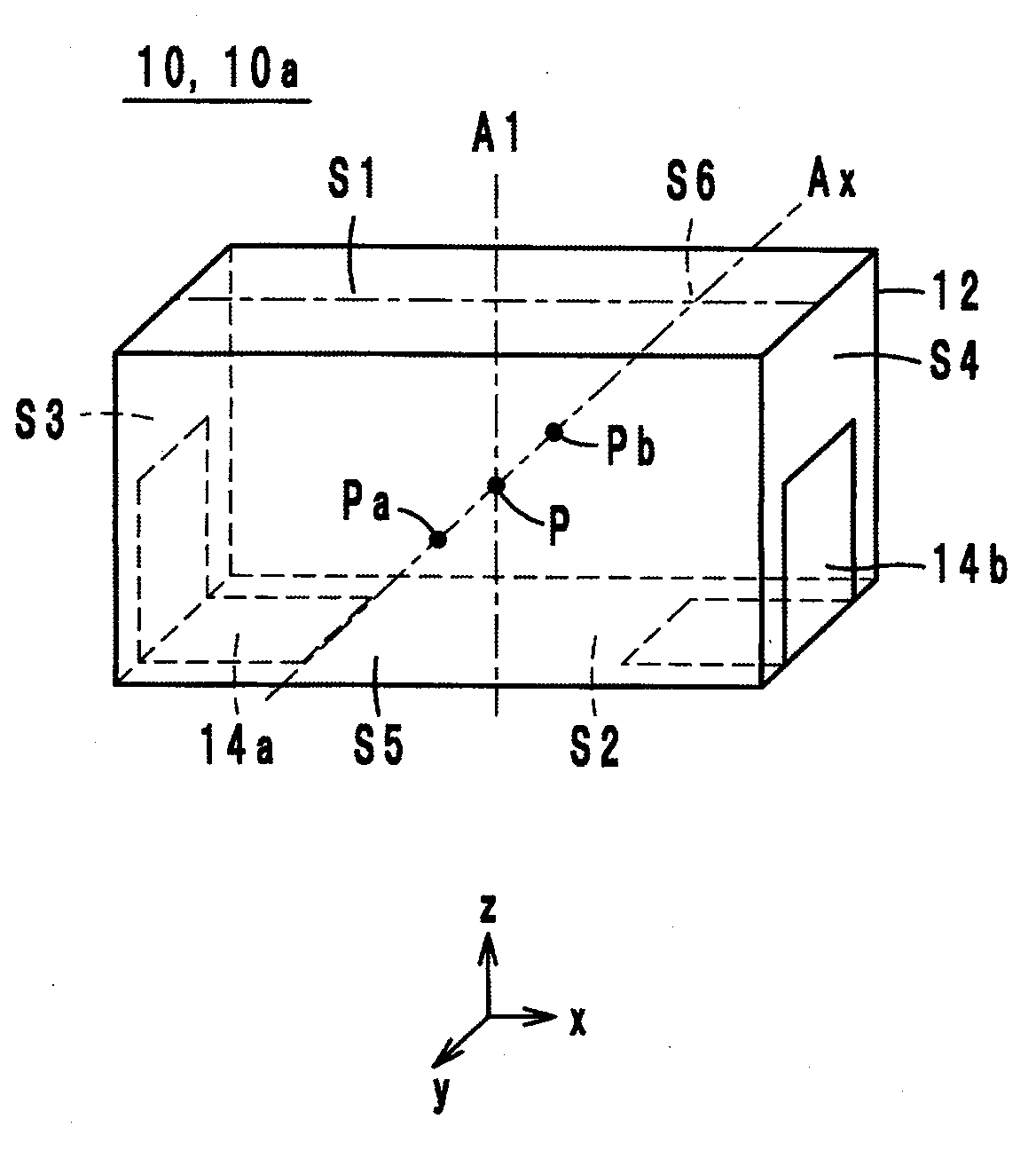
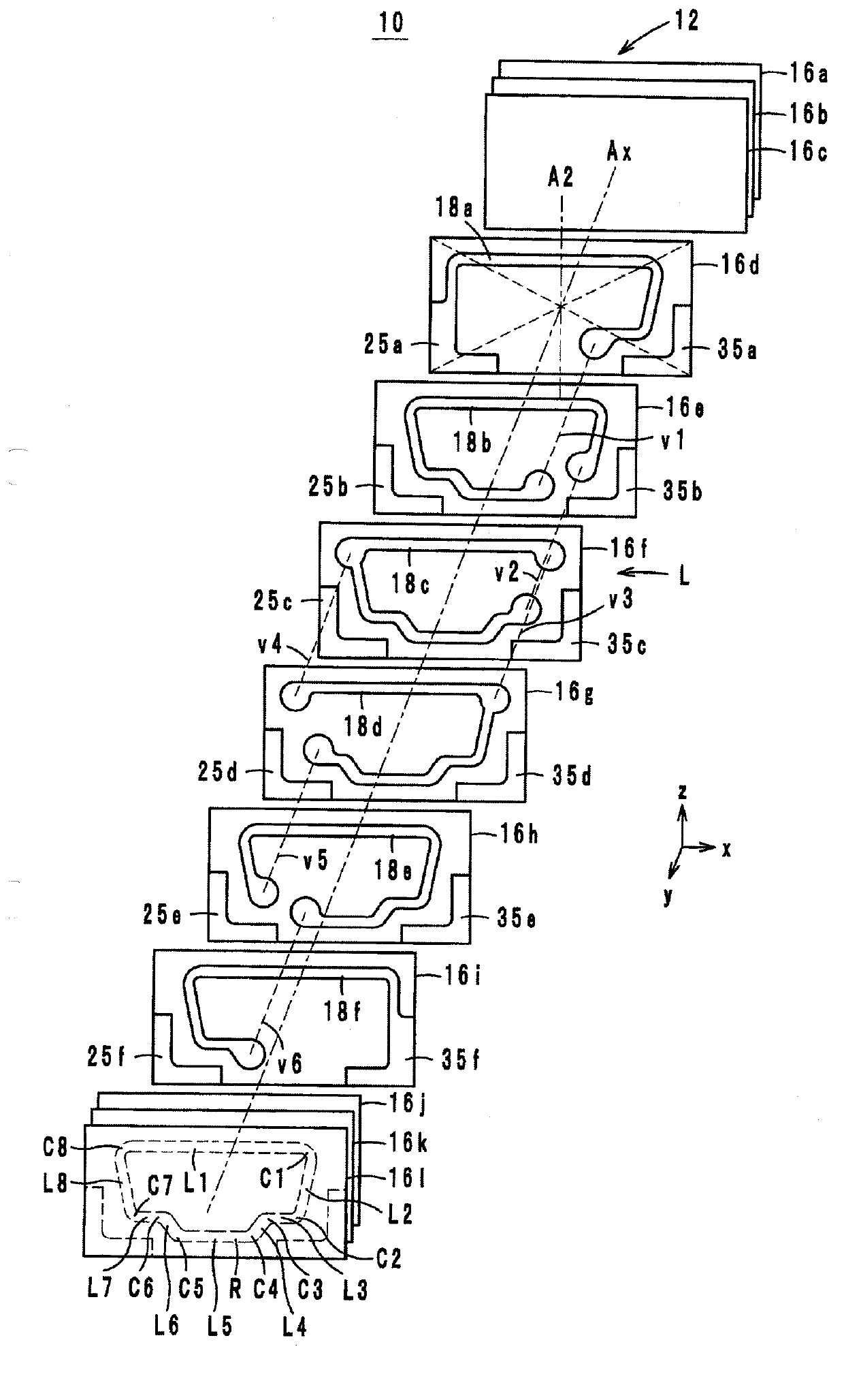
[0019] Hereinafter, the configuration of an electronic component according to an embodiment will be described with reference to the drawings. figure 1 It is an external perspective view of the electronic component 10 according to one embodiment. figure 2 Yes figure 1 An exploded perspective view of the electronic component 10. Hereinafter, the stacking direction of the electronic component 10 is defined as the y-axis direction. In addition, the direction in which the long side of the electronic component 10 extends when viewed in plan from the y-axis direction is defined as the x-axis direction, and the direction in which the short side of the electronic component 10 extends is defined as the z-axis direction.

[0020] Electronic components 10 such as figure 1 with figure 2 As shown, it includes a laminate 12, extern...


PUM


Abstract

A multilayer body is formed of a plurality of insulator layers that are stacked on top of one another. A coil is a helical coil provided in the multilayer body and includes a plurality of coil conductor layers that are superposed with one another so as to form a ring-shaped path when seen in plan view from a stacking direction and a plurality of via hole conductors that connect the plurality of coil conductor layers together. The path includes corners that project outward and corners that project inward. Each of the via hole conductors are provided at one of the corners, which project outward.

Description

Technical field [0001] The present invention relates to an electronic component, and more specifically, to an electronic component including a laminated body with a built-in coil. Background technique [0002] As a conventional electronic component, for example, a laminated inductor described in Patent Document 1 is known. Figure 7 It is an exploded perspective view of the laminated body 500 of the laminated inductor described in Patent Document 1. [0003] The laminated body 500 of the laminated inductor described in Patent Document 1 is constituted by laminating a plurality of rectangular insulating layers 502. An L-shaped external electrode pattern 506 is provided at the corner of the insulator layer 502. The plurality of external electrode patterns 506 overlap each other to form external electrodes. In addition, the insulator layer 502 has a coil conductor pattern 504 in which a part of the loop is cut out. The coil conductor pattern 504 has a shape imitating the external el...

Claims


Application Information

Patent Timeline
IPC IPC(8): H01F17/00H01F27/28H01F27/30
CPCH01F17/0013H01F27/292H01F17/00H01F27/00H01F27/29
Inventor 世古笃史三崎胜弘
Owner MURATA MFG CO LTD
Why Eureka
Try Eureka