

Method and device for topology discovery of matrix stacking system
A stacking system and topology discovery technology, applied in the field of network communication, can solve the problems of restricting the expansion and application of the matrix stacking system, and achieve the effect of accurate collection and expansion of the stacking system
- Summary
- Abstract
- Description
- Claims
- Application Information
AI Technical Summary
Problems solved by technology
Method used
Image

Examples
Embodiment 1
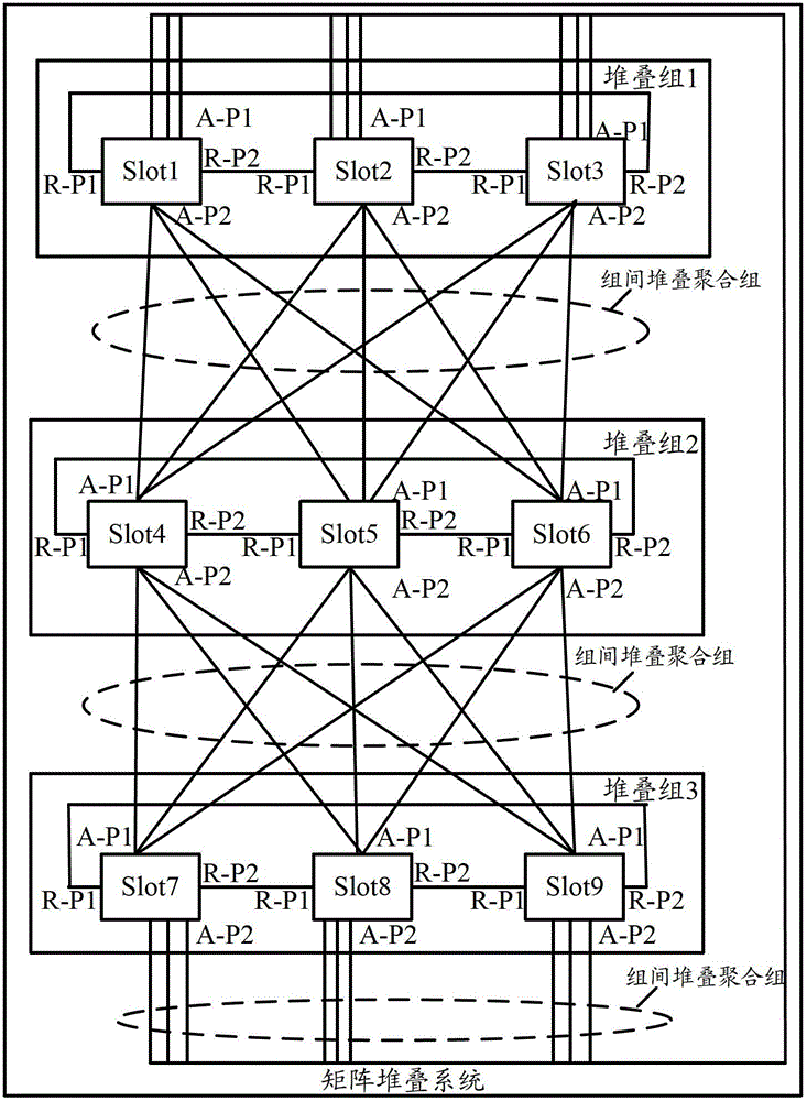
[0030] by figure 2 The matrix stack system shown is an example, in figure 2 The stacking system shown includes the following three stacking groups: stacking group 1 to stacking group 3 . The slots in each stacking group from stacking group 1 to stacking group 3 are connected in a ring, and the first group of internal stacking ports (identified by R-P1) and the second group of internal stacking ports (identified by R-P2) are all set. R-P1 and R-P2 of two adjacent slots in the same stacking group are interconnected through stacking links to form a ring connection between slots in the stacking group. by figure 2 Take stacking group 1 as an example. In stacking group 1, Slot1 is adjacent to Slot2, Slot2 is adjacent to Slot3, and Slot3 is adjacent to Slot1. According to the R-P1 and R- P2 is connected through a stacking link, then R-P2 of Slot1 is connected to R-P1 of Slot2 through a stacking link, R-P2 of Slot2 is connected to R-P1 of Slot3 through a stacking link, and R-P2 ...
Embodiment 2
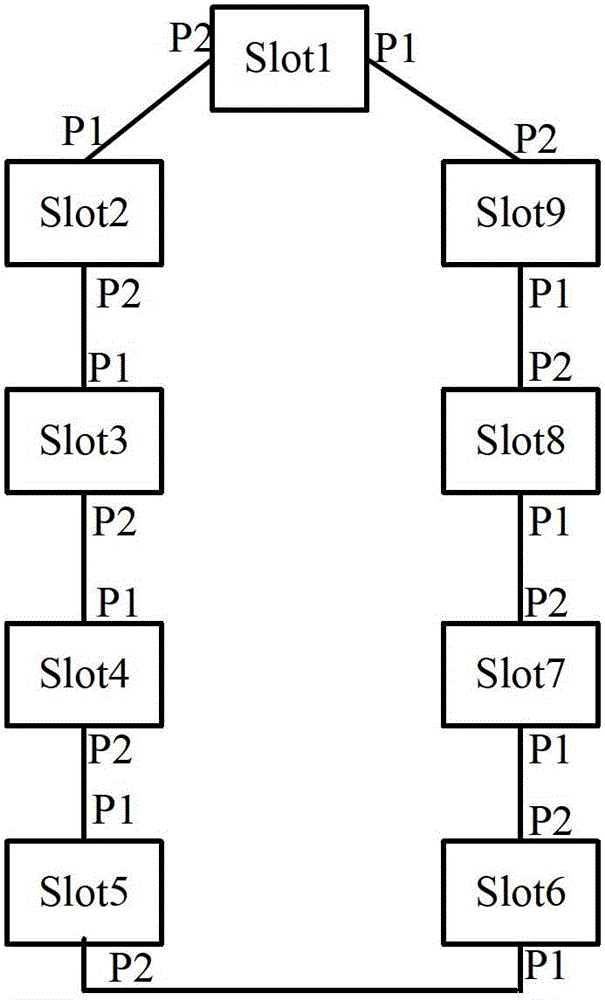
[0067] by image 3 Stacking system shown as an example, the image 3 The stacking system shown includes the following three stacking groups: stacking group 1 to stacking group 3 . The Slots in each stacking group from stacking group 1 to stacking group 3 are connected in a chain, and all have the first group of internal stacking ports (identified by R-P1) and the second group of internal stacking ports (identified by R-P2), Among them, for the Slots at both ends of each stacking group from stacking group 1 to stacking group 3, only the stacking port in one group is valid, and the stacking port in the other group is invalid, and the valid stacking port identifications of the two ends of the Slot in each stacking group are different. However, both R-P1 and R-P2 of the Slots between the two ends of the stacking group are valid. by image 3 Take stack group 1 as an example. In stack group 1, R-P1 and R-P2 are set for Slot1 to Slot3. The effective stack port of Slot1 is R-P2, an...
Embodiment 3
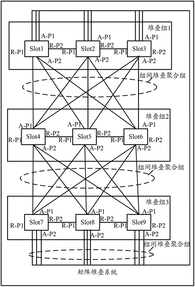
[0098] by Figure 4 The matrix stack system shown is an example, in Figure 4 The stacking system shown includes the following three stacking groups: stacking group 1 to stacking group 3 . The Slots in each stacking group from stacking group 1 to stacking group 3 are connected in a chain. The Slots at both ends of each stacking group have only one stacking port in the group, and the Slots between the two ends of the Slots in each stacking group are provided with two Intra-group stacking port. by Figure 4 The stacking group 1 shown is taken as an example. In stacking group 1, Slot1 is used as the Slot at one end of stacking group 1, and a stack port in the group (identified by R-P2) is set. Slot3 is used as the Slot at the other end of stacking group 1. Set a The stack port in the group (marked by R-P1), and Slot2 is used as the slot between the two ends of the stacking group 1. Set two stack ports in the group, marked by R-P1 and R-P2 respectively. In stacking group 1, R-...
PUM
 Abstract
Description
Claims
Application Information