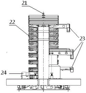
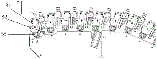
[0044] Such as figure 1 As shown, this system is a comprehensive vehicle inspection system, including chassis vehicle 1, strobe indicator light 2, sub-frame 3, power wall box, sliding shelter 5, front fixed retaining wall 6, working area small cabin 7, working Large compartment 8, accessory box 9, rangefinder 10, throttle door 11, such as figure 2 As shown, the sensor bracket is installed in the sliding shelter 5. The chassis vehicle is the mobile measurement platform of the system, and provides a vehicle-carrying platform for the equipment of the tunnel measurement system. Chassis 1 adopts a light truck with great traction and good maneuverability. The whole car adopts an air spring shock absorption system to ensure the safety and stability of the equipment. The synchronization and signal processing device is installed in the small cabin 7 in the working area, and the data acquisition and processing device and the power supply device are installed in the large cabin 8 in the working area.
[0045] Such as image 3 , Figure 4 As shown, the sensor bracket is a system sensor equipment carrying device, which is installed on the chassis vehicle through a horizontal rotating shaft, and can rotate 90° in a horizontal range. When the tunnel car is measuring during the traveling process, the left and right rotating sensor brackets can be rotated to realize the collection of the left and right half of the tunnel data. There is no need to close the road or reverse the journey. When actually doing the project, there is no need to walk through the repeated sections, which is greatly Improved detection efficiency.
[0046] The sensor bracket includes a horizontal base and a fan-shaped stand. A laser scanner 24 is installed on the horizontal base. An infrared thermal imager is installed on the side of the fan-shaped stand. The infrared thermal imager is used to collect the temperature data of the inner wall of the tunnel; the infrared thermal imager adopts Two infrared cameras with an imaging angle of 90° or three infrared cameras with an imaging angle of 45°. The infrared thermal imager is used to collect the temperature data of the inner wall of the tunnel, and generate a heat map through post data processing. A laser scanner is installed on the horizontal base, and the laser scanner is connected to the synchronization and signal processing device and the data acquisition and processing device, which is used to complete the collection of the contour data of the full section of the tunnel when the vehicle is traveling.
[0047] On the curved surface of the top of the fan-shaped stand, 17 groups of combined LED illuminators and 16 area array cameras are sequentially installed. The emitting direction of different LED illuminating lamps gradually changes according to the arrangement order of the bright units. The cumulative emitting light angle of all LED illuminating lamps on the vertical plane covers 90 degrees, and the light projected on the inner wall of the tunnel by adjacent light bands is connected without shadows . The shooting angles of all area array cameras gradually change in the order of the area array cameras, and the cumulative shooting angle of the area array cameras on the vertical plane covers 90 degrees.
[0048] The laser scanner completes the collection of the profile data of the full section of the tunnel when the vehicle is traveling; the LED illuminator is used to illuminate the top surface of the tunnel arc, and provides the light source for the area array camera to capture the image of the top surface of the tunnel arc; the synchronization and signal processing device is a laser Scanners and area array cameras provide synchronization and signal processing; data acquisition and processing devices collect and process signals from laser scanners and area array cameras; power supply devices include laser scanners, area array cameras, synchronization and signal processing devices, data acquisition and The processing device provides working power.
[0049] Such as Figure 5 As shown, each group of LED lighting lamps includes a lamp holder 31, each LED lamp holder is a stepped-shaped elongated structure, a long combined LED installed on the high position of the lamp holder 31 is the main light source, and the low position A long combined LED is installed as a secondary light source. This component can be adjusted by ±5° in the Y direction by adjusting nut A. The camera can be adjusted by ±5° in the Y direction by adjusting the nut B. The installation position and adjustment angle of the LED lights and the camera are designed and calculated according to the two-lane tunnel model. The main purpose is to realize the stitching of cross-sectional image data.
[0050] The installation method of a single LED is horizontal, such as Figure 7 Shown. The use of this installation method mainly takes into account the characteristics of the light projection area and light intensity of a single LED, such as Image 6 As shown, the lighting shape of a single LED on the inner wall of the tunnel is an elliptical area, and the brightness is not uniform, but gradually weakens from the center to the periphery. Taking into account the lighting characteristics of a single LED, in order to form an illuminated strip in the X direction of the cross section of the inner wall of the tunnel, the installation method of the LED light needs to be adjusted in combination to achieve a uniform illumination area larger than the camera shooting area, so as to assist the camera illumination. Figure 7 That is, it is a schematic diagram of the light band generated by multiple single LED lighting. The adjacent single LED lighting area in the figure overlaps to a certain extent. Its function is to increase the brightness of the lighting through superposition, and finally obtain a strip-shaped rectangular lighting with uniform brightness. area.
[0051] The projection surface of the main light source LED lamp is shown as Figure 8 Shown. 41 and 42 respectively indicate the light path emitted by the main light source of the 16th and 15th LED lights, and the light projection area of the light path on the inner wall of the tunnel. There is a gap 43 between the projections of the two adjacent main light sources on the inner wall of the tunnel 43 and the projections of the other two adjacent main light sources on the inner wall of the tunnel. This is not conducive to the image acquisition of the dark shadow irradiated by the tunnel wall light source by the area array CCD camera. In order to satisfy that the LED light source covers the entire half-width tunnel inner wall, a secondary light source is added. The projection surface of the secondary light source is shown as Picture 9 As shown, where 51 and 52 respectively represent the light path emitted by the 16th and 15th LED lights from the secondary light source, and the light projection area of the light path on the inner wall of the tunnel. There is a gap 53 in the projections of the 14th and 15th adjacent secondary light sources on the inner wall of the tunnel. There is also a gap between the projections of the other two adjacent secondary light sources on the inner wall of the tunnel. However, the projection gap of the secondary light source is located in the effective projection area of the main light source, and the projection gap of the main light source on the inner wall of the tunnel is located in the effective projection area of the secondary light source. In this way, the secondary light source and the main light source complement and cooperate with each other, so that there is no light source projection gap on the inner wall of the tunnel, and at the same time, the illumination on the tunnel wall is enhanced. This specific implementation gives the installation position coordinates of the light source as Picture 10 As shown, the installation angle coordinates of the light source are as Picture 11 Shown.
[0052] An area array CCD camera is installed between two adjacent LED lamp holders. There are 16 area array CCD cameras between 17 LED lamp holders. The projection surface of the area array CCD camera is shown as Picture 12 Shown. Among them, reference number 61 refers to the scanning area of the 16th camera, reference number 63 refers to the scanning area of the 15th camera, and reference number 62 refers to the scanning overlap area of the 16th and 15th cameras. Since the focal length and object distance of each camera are different, the projection area of each camera is different. In order to fully cover the inner wall of 1/2 tunnel, the installation position of each camera needs to be accurately calculated. This specific implementation gives The coordinate position of the area array CCD camera is as Figure 13 As shown, the camera installation angle position is as Figure 14 Shown. Due to the calibration of the later system, the position of the camera needs to be fine-tuned, so the installation angle of a single camera can be adjusted within ±5°.
[0053] The principle of the tunnel rapid measurement system of the present invention is:
[0054] The camera collects the image data of the inner wall of the tunnel, the scanner collects the profile data of the cross section of the tunnel, and the infrared thermal imager collects the temperature information of the inner wall of the tunnel. For all the collected sensor data, perform data fusion processing in the later stage, and attach the image data and infrared data to the 3D model of the tunnel to restore the true health of the tunnel. Combined with the encoder data in the system, the geographic location information of the disease is also recorded. The characteristics and physical locations of all diseases have been accurately recorded, and the report data of later production can be used for reference by the maintenance department.
[0055] The currently used tunnel crack detection method has low efficiency, requires traffic closure, high risk to personnel, poor applicability for general film, and does not have generalization. The present invention uses a multi-sensor combination method to collect images of the inner wall of the tunnel through machine vision Data, infrared thermal imaging camera to collect the temperature information of the inner wall of the tunnel, the scanner to collect the cross-sectional profile information of the tunnel, the encoder and GPS to mark the collected data by the travel time and physical location, and it can be collected in one engineering inspection Multiple disease data of the tunnel, with high efficiency and good security, applicable to all tunnels;
[0056] The invention combines the appearance characteristics of the tunnel itself in the actual application process to independently design a unique sensor support platform. During the traveling process of the tunnel car, the left and right half of the tunnel data can be collected through the rotation of the rotating support, without road closure. There is also no need for reverse travel, and no need to go through repeated sections when actually doing the project, which greatly improves the detection efficiency;
[0057] Finally, it should be noted that the above specific implementations are only used to illustrate the technical solutions of the present invention and not to limit them. Although the present invention has been described in detail with reference to the preferred embodiments, those of ordinary skill in the art should understand that the Modifications or equivalent replacements of the technical solutions without departing from the spirit and scope of the technical solutions of the present invention should be covered by the scope of the claims of the present invention.