Supercharge Your Innovation With Domain-Expert AI Agents!

Light guide alignment device for power tool

A technology of electric tools and guiding devices, which is applied to the attachments of sawing machines, manufacturing tools, metal processing equipment, etc., and can solve problems such as difficult to see shadow lines and user confusion

Inactive Publication Date: 2013-07-24
ROBERT BOSCH GMBH
View PDF0 Cites 0 Cited by
  • Summary
  • Abstract
  • Description
  • Claims
  • Application Information

AI Technical Summary

Problems solved by technology

For example, in high light exposure conditions, it is difficult to see cast shadow lines
Also, hatching can confuse the user, since the cut marks are actually dark lines rather than light lines

Method used


Image

  • Light guide alignment device for power tool
  • Light guide alignment device for power tool
  • Light guide alignment device for power tool

Examples


Embodiment Construction

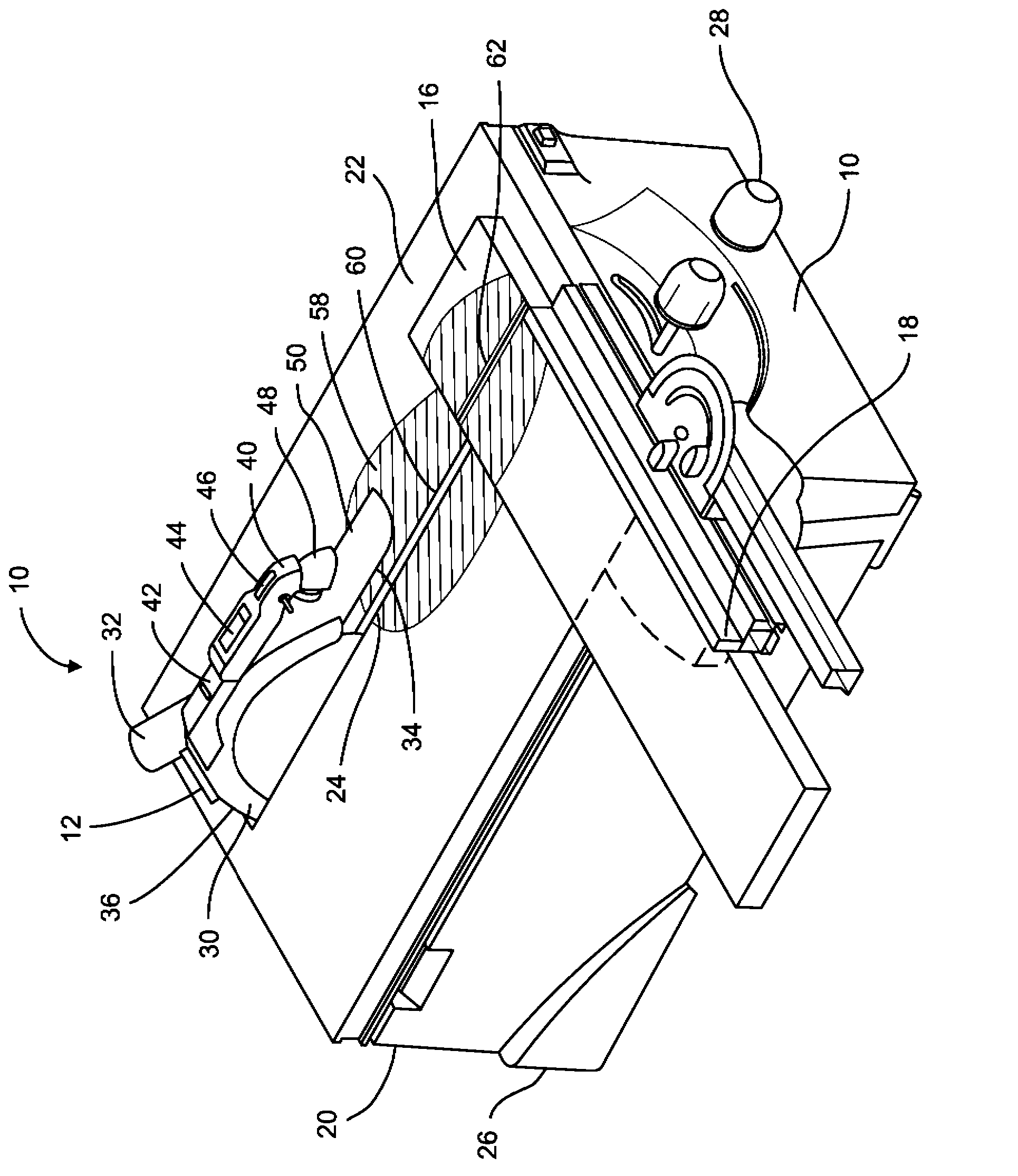
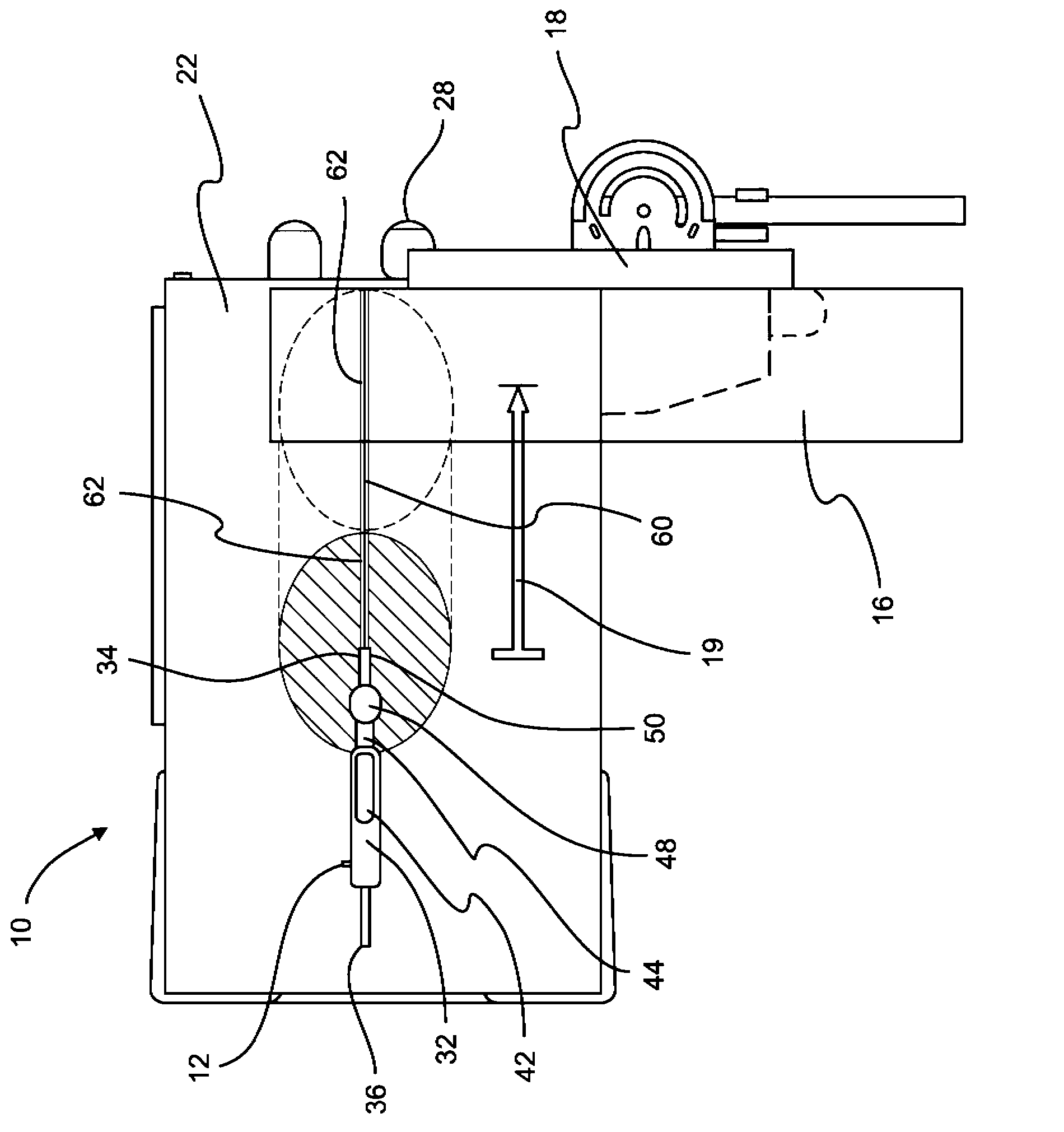
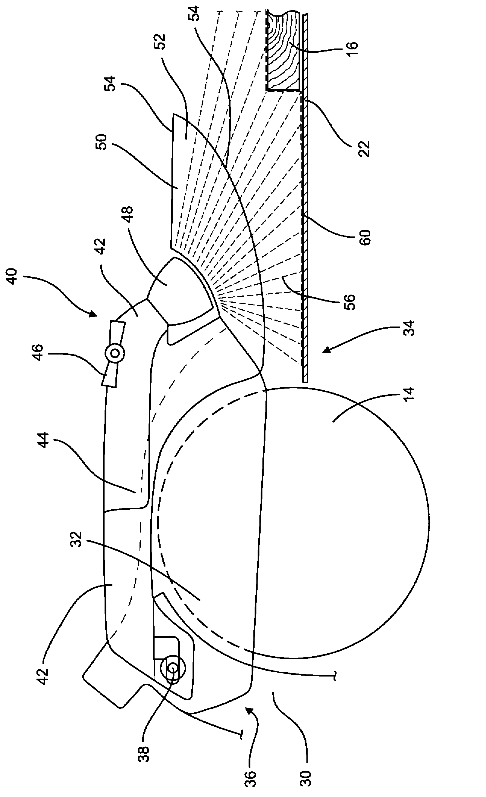
[0023] See in general Figure 1-3 , Shows an embodiment of a power tool with a light guiding and aligning device. The power tool is shown in the form of a table saw 10 including a saw 12 with a circular saw blade 14. The alignment assembly 40 with the light guiding device 50 is mounted to the front side of the saw 12. The light guiding device 50 is configured to guide the light beam from the light source 48 to a position in front of the circular saw blade and to provide a kerf mark 60 for the circular saw blade.

[0024] Those skilled in the art can recognize that the table saw 10 may include a movable bracket (not shown) that is coupled to the underside of the table top 22. The stand holds the saw 12 so that the circular saw blade 14 extends through the opening 24 formed in the table top 22. The opening 24 in the table top 40 is generally provided in the form of an elongated slit, thereby allowing the saw blade 14 to move along the table top 22 in a linear direction. The circ...


PUM


Abstract

A power tool (10) with an alignment device (40) includes a circular saw blade (14) which defines a front side (34) and a rear side (36) of the power tool (10). The power tool (10) further includes a light source (48) and a light guide (50) positioned on the front side (34) of the power tool (10). The light guide (50) is configured to direct a beam (56) of light from the light source (48) to a position in front of the circular saw blade (14) and provide a kerf indicator (60) for the circular saw blade (14). In various embodiments, the kerf indicator (60) may be a shaded line or an illuminated line. The light guide (50) may be connected to a blade guard (32) that at least partially covers the circular saw blade (14). In at least one embodiment, the light guide (50) is provided on the front side (34) of the power tool (10) as an elongated fin substantially aligned with the circular saw blade (14).

Description

Technical field [0001] The present invention relates to the field of electric tools, in particular to an alignment device for electric tools. Background technique [0002] Table saws and other power tools with circular saw blades are configured to cut workpieces of various shapes and sizes. In order to create a cut in the workpiece, the user either moves the saw along a straight line to engage the workpiece, or moves the workpiece along a straight line to engage the saw. The user tries his best to maintain the correct alignment between the workpiece and the saw to provide a cut at the desired location on the workpiece. Therefore, users of these saws need to visually determine where the cut will be made on the workpiece before and during the cutting process. [0003] To help users make cuts at desired locations on the workpiece, some electric workers include lights. If the saw is moving in a straight line relative to the workpiece, the light can be used to illuminate the work are...

Claims


Application Information

Patent Timeline
IPC IPC(8): B23D59/00
CPCB23D59/003Y10T83/828Y10T83/7684
Inventor J·S·克格尔
Owner ROBERT BOSCH GMBH
Features
  • R&D
  • Intellectual Property
  • Life Sciences
  • Materials
  • Tech Scout
  • Unparalleled Data Quality
  • Higher Quality Content
  • 60% Fewer Hallucinations
Learn More