
Air channel control device and air channel control system

A gas circuit control and control circuit technology, which is applied in the direction of electric fluid pressure control, etc., can solve the problems of inconvenient debugging, bulkiness, and low control sensitivity on site, and achieve convenient on-site debugging, high control sensitivity, and improved control sensitivity. Effect

Inactive Publication Date: 2013-07-31
HUAZHONG UNIV OF SCI & TECH
View PDF5 Cites 13 Cited by
  • Summary
  • Abstract
  • Description
  • Claims
  • Application Information

AI Technical Summary

Problems solved by technology

[0004] Aiming at the defects of the prior art, the object of the present invention is to provide a gas circuit control device, aiming at solving the problems of low control sensitivity, heavy weight and inconvenient on-site debugging in the existing gas circuit control device

Method used


Image

  • Air channel control device and air channel control system
  • Air channel control device and air channel control system
  • Air channel control device and air channel control system

Examples


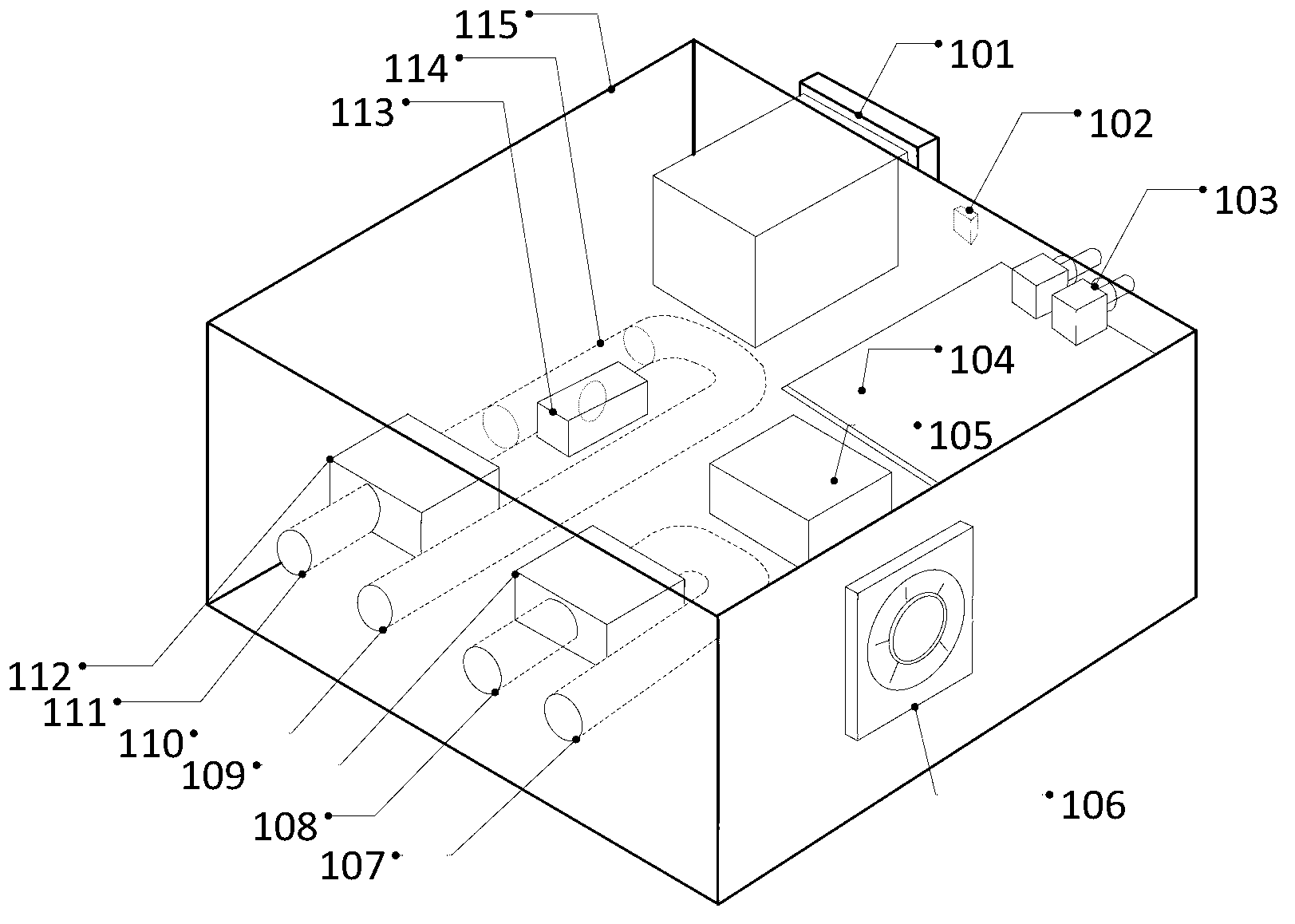
Embodiment Construction

[0027] In order to make the object, technical solution and advantages of the present invention clearer, the present invention will be further described in detail below in conjunction with the accompanying drawings and embodiments. It should be understood that the specific embodiments described here are only used to explain the present invention, not to limit the present invention.

[0028] have to be aware of is, figure 1 It is a schematic diagram of the structure drawn assuming that the upper cover and the rear cover of the gas circuit control device are transparent, Figure 4 The arrows in indicate the flow direction of the gas, and the inflatable entity is used as an example to inflate the inflatable entity, figure 1 with Figure 4 The dotted line in shows the trachea.

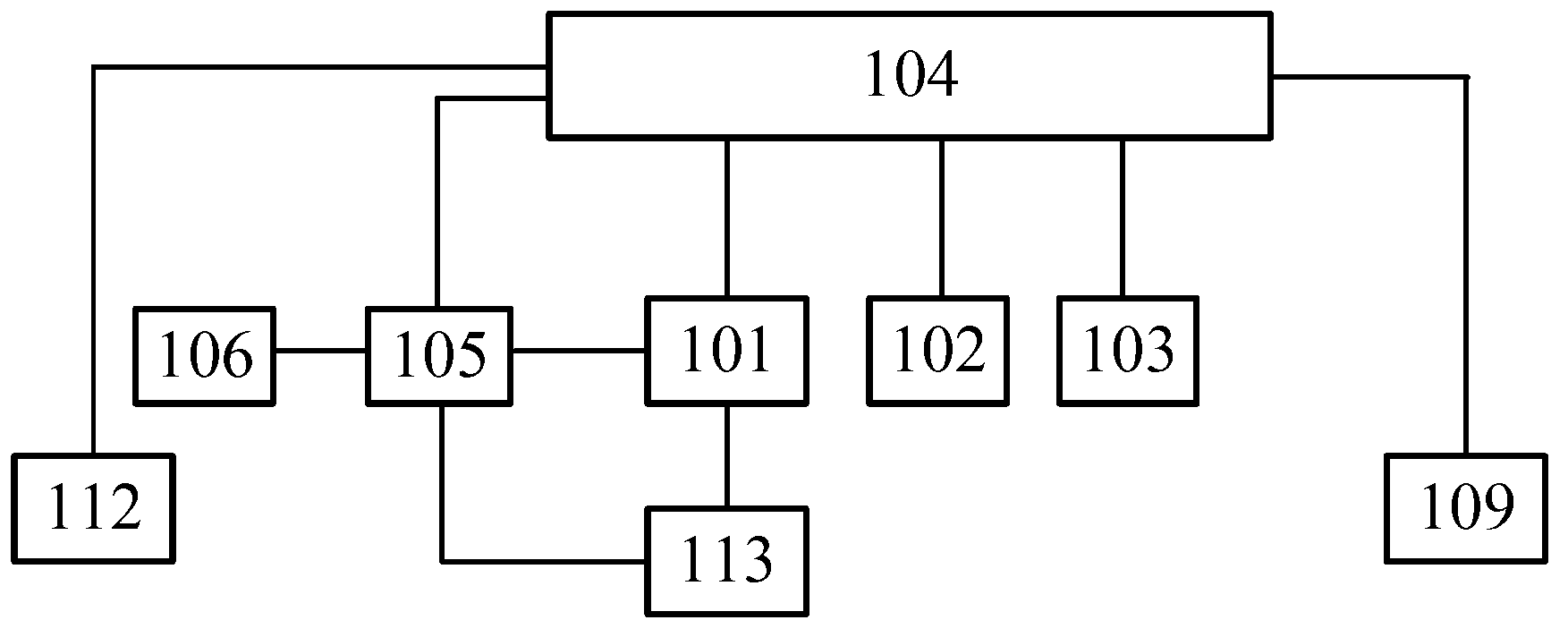
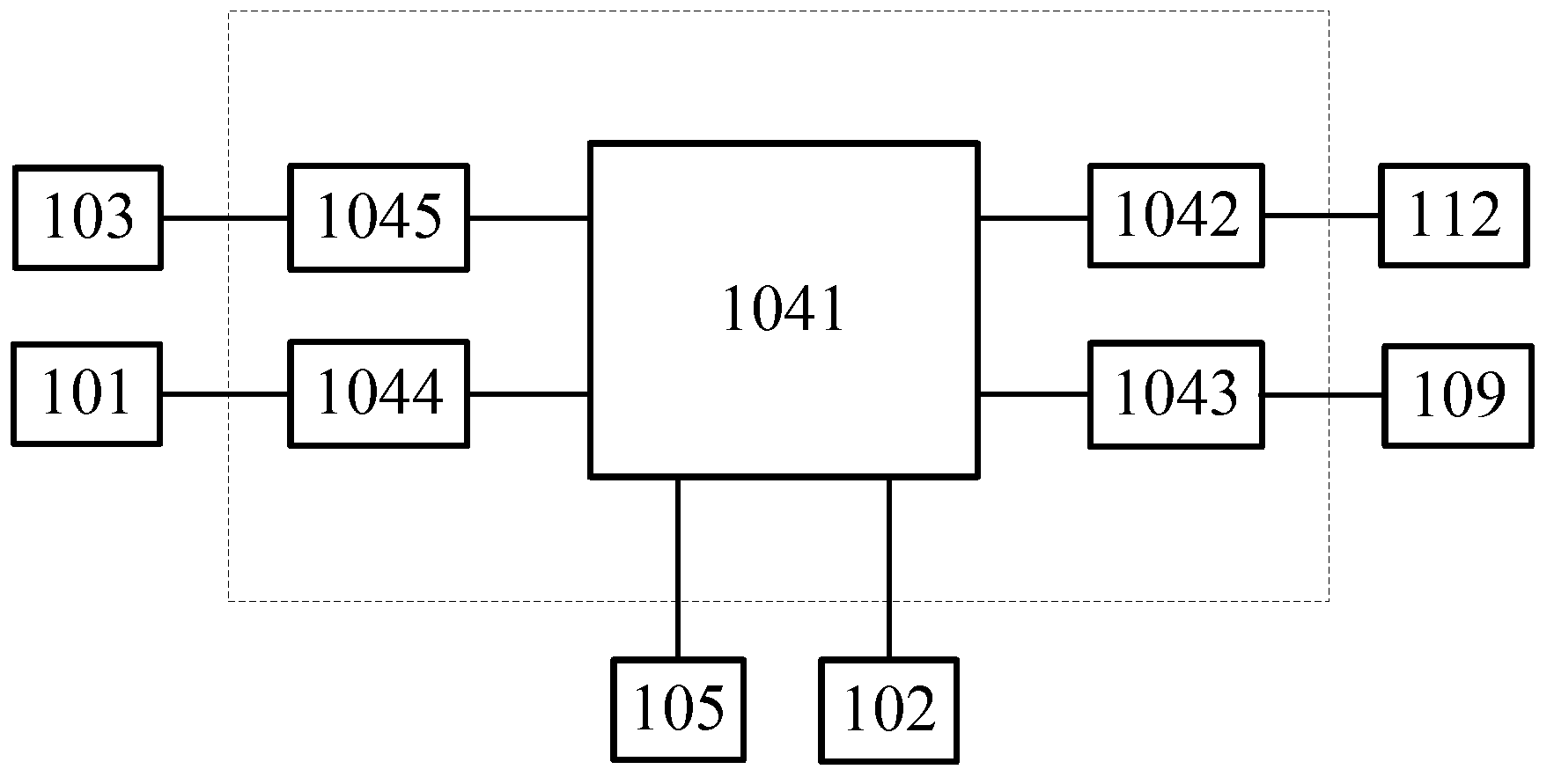
[0029] Such as figure 1 As shown, the gas path control device 1 of the present invention includes a smart meter head 101, a deflation button 102, an optical fiber adapter 103, a control circuit 104, a p...


PUM


Abstract

The invention discloses an air channel control device which comprises an intelligent gauge outfit, a vent button, optical fiber adaptors, a control circuit, a power supply, an extraction fan, an exhaust joint, a vent joint, an inflation joint, an air supply joint, a vent electromagnetic valve, an inflation electromagnetic valve, a pressure transmitter and a T-shaped three-way joint, wherein an inlet end of the inflation electromagnetic valve is connected with the air supply joint; an outlet end of the inflation electromagnetic valve is connected with one port of the T-shaped three-way joint; another port of the T-shaped three-way joint is connected with the pressure transmitter; another port of the T-shaped three-way joint is connected with the inflation joint; an inlet end of the vent electromagnetic valve is connected with the vent joint; an outlet end of the vent electromagnetic valve is connected with the exhaust joint; and the control circuit is connected with the intelligent gauge outfit, the vent button, the optical fiber adaptors, the power supply, the vent electromagnetic valve and the inflation electromagnetic valve respectively, and used for obtaining control information from the intelligent gauge outfit. The air channel control device can solve the problems that the existing air channel control device is low in control sensitivity, relatively heavy, and inconvenient to debug on site.

Description

technical field [0001] The invention belongs to the field of electrical devices and gas path control, and more specifically relates to a gas path control device and a gas path control system. Background technique [0002] The gas circuit control device is designed to serve various inflatable entities in the field of gas circuit control, such as common inflatable entities in high-voltage engineering, to ensure their reliable operation. According to the requirements of the inflatable entity or other inflatable entities for various parameters of the internal gas, the gas circuit control device is used to design the gas circuit control system to achieve reliable control of inflation, pressure maintenance and deflation. [0003] Because the existing gas circuit control device uses an electric valve as an actuator, it takes a long time to complete the opening or closing action, resulting in low control sensitivity of the device. At the same time, the volume of the electric valve ...

Claims


Application Information

Patent Timeline
Patent Type & Authority Applications(China)
IPC IPC(8): G05D16/20
Inventor 李黎葛亚峰张钦林福昌鲍超斌
Owner HUAZHONG UNIV OF SCI & TECH
Learn More