Flyback converter with primary side voltage sensing and overvoltage protection during low load operation

A technology of converters and transformers, applied in the field of DC-DC flyback converters

Active Publication Date: 2013-07-31
ANALOG DEVICES INT UNLTD
View PDF9 Cites 43 Cited by
  • Summary
  • Abstract
  • Description
  • Claims
  • Application Information

AI Technical Summary

Problems solved by technology

However, when the actual load drops below the threshold current, the minimum duty cycle requir

Method used


Image

  • Flyback converter with primary side voltage sensing and overvoltage protection during low load operation
  • Flyback converter with primary side voltage sensing and overvoltage protection during low load operation
  • Flyback converter with primary side voltage sensing and overvoltage protection during low load operation

Examples


Embodiment Construction

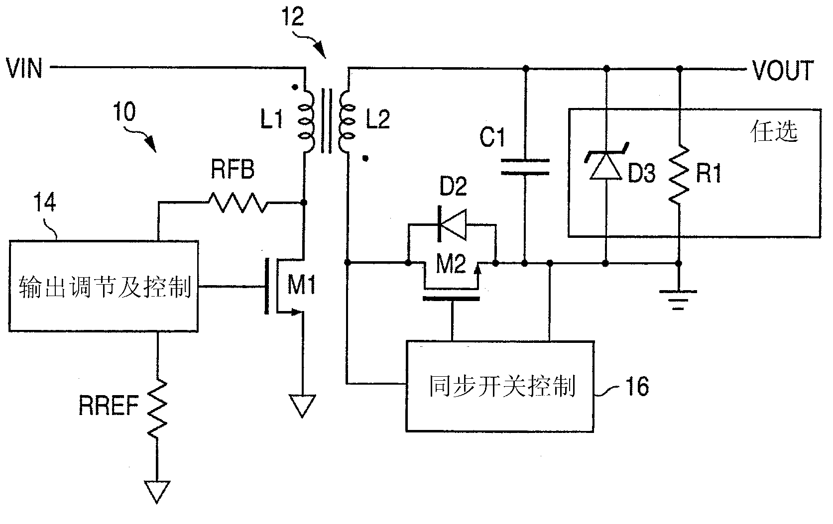
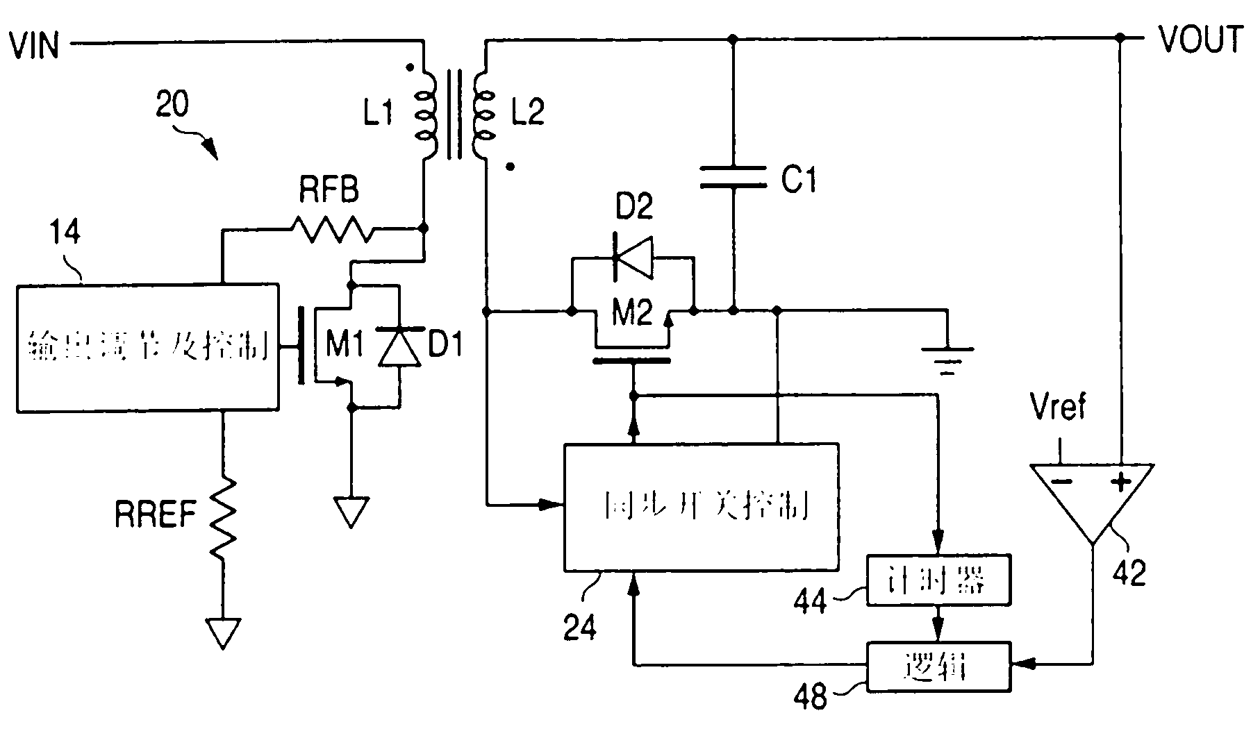
[0034] image 3 represents any of many types of flyback converters that use primary-side sensing of the output voltage VOUT. Since the present invention only concerns the operation of the converter during light load current conditions, any conventional aspect of the flyback converter can be used for medium to high load currents when the converter is operating in discontinuous mode and an overvoltage occurs. Since this conventional circuit is well known and there are various types such as current mode, voltage mode, variable frequency, fixed frequency, etc., it is not necessary to describe this conventional circuit in detail. The description of conventional aspects of the converter 10 of Figure 1 applies to image 3 The converter 20.

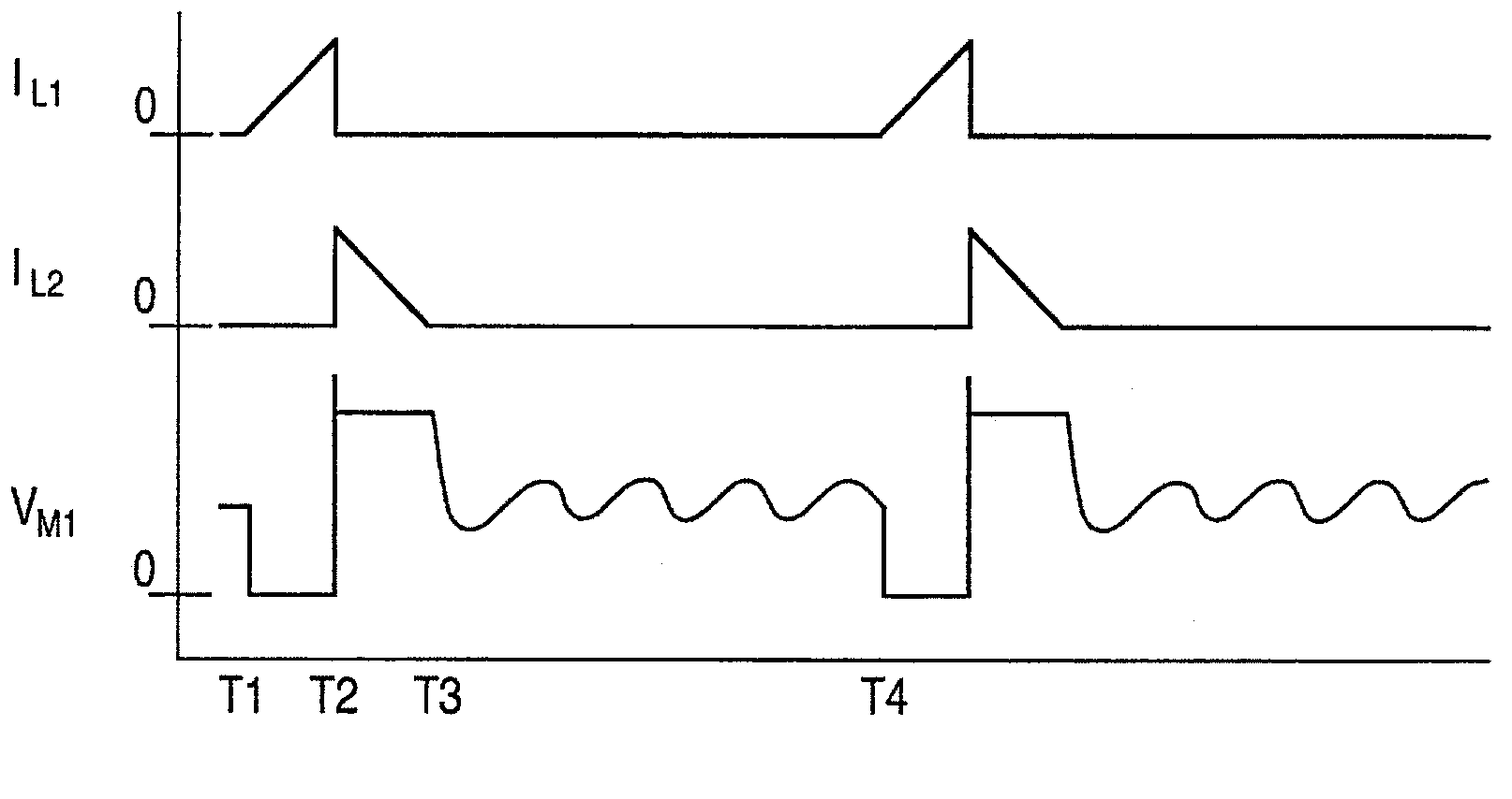
[0035] For medium to high load current operation, converter 20 periodically turns on MOSFET M1 to charge primary winding L1 . The on-time of MOSFET M1 depends on the feedback voltage (related to VOUT) at the drain of MOSFET M1 sampled at the tim...


PUM


Abstract

A flyback converter (20) uses primary side sensing to sense the output voltage for regulating feedback. The flyback converter comprises a transformer with a primary winding (L1) and a secondary winding (L2), a first transistor (M1) coupled to the primary winding for conducting a current through the primary winding when the first transistor is on a second transistor (M2) for conducting a current through the secondary winding when the second transistor is on a regulator (14) coupled to the first transistor for controlling a duty cycle of the first transistor to regulate an output voltage of the converter, the regulator being configured to control the first transistor to have a minimum duty cycle, an output capacitor (C1) coupled to an output terminal of the converter, a synchronous rectifier controller (24) coupled to the second transistor for controlling the second transistor to be on or off, a comparator (42) having one input coupled to receive a voltage corresponding to the output voltage of the converter and having another input connected to a reference voltage representing a threshold voltage exceeding a regulated voltage of the converter, wherein triggering of the comparator signifies an over-voltage condition, an output of the comparator being coupled so as to control the synchronous rectifier controller to turn the second transistor on for an interval to conduct a reverse current through the secondary winding, upon an over-voltage condition being detected, to reduce the output voltage of the converter to mitigate the over-voltage condition, and a diode (D1) coupled to the primary winding to conduct a current through the primary winding after the interval without turning on the first transistor, such that power is transferred from a secondary side of the transformer to the power source while mitigating the over-voltage condition.

Description

technical field [0001] The present invention relates to DC-DC flyback converters using synchronous rectifiers, and more particularly to such flyback converters using primary side sensing to detect output voltage. Background technique [0002] DC-DC flyback converters using synchronous rectifiers are well known. When isolation between the input and output stages is required, the output voltage can be sensed by various methods for regulation feedback. Some ways of delivering the output voltage while maintaining isolation include using an optocoupler on the primary side of the transformer or using a tertiary winding. However, these approaches require additional circuitry, space, power and cost. A more subtle way of detecting the output voltage is to sense the voltage at the power switch terminals when the power switch is turned off during the discharge (or flyback) cycle of the converter. This sensed voltage is substantially proportional to the output voltage. However, in o...

Claims


Application Information

Patent Timeline
IPC IPC(8): H02M3/335H02M1/00H02M1/32
CPCY02B70/16H02M1/32Y02B70/1475H02M2001/0032H02M3/33523H02M3/33592H02M3/33584H02M1/0032Y02B70/10
Inventor 约翰·D·莫里斯迈克尔·G·内格雷特陈敏
Owner ANALOG DEVICES INT UNLTD
Why Eureka
Try Eureka