Supercharge Your Innovation With Domain-Expert AI Agents!

Telephone receiver with improved transmission mechanism

An improved technology for receivers, applied in the direction of sensors, speaker screens, transducer shells/cabinets/brackets, etc., can solve the problems of increased volume of receivers, howling of receivers, increased production costs, etc., and achieve audio output improvement and offset Effect of axial vibration and vibration reduction

Active Publication Date: 2013-07-31
SUZHOU YICHUAN TECH CO LTD
View PDF4 Cites 15 Cited by
  • Summary
  • Abstract
  • Description
  • Claims
  • Application Information

AI Technical Summary

Problems solved by technology

However, with the miniaturization of the moving iron unit in the receiver, the electro-acoustic conversion efficiency of the moving iron unit will also decrease. In order to obtain better voice quality, the form of multi-unit combination is currently used to meet the requirements, but it will come What is the increase in production costs and the increase in size of the receiver
At the same time, the axial vibration of the receiver shell due to the vibration of the diaphragm will cause the howling of the receiver and affect the output of the receiver's speech quality.

Method used


Image

  • Telephone receiver with improved transmission mechanism
  • Telephone receiver with improved transmission mechanism
  • Telephone receiver with improved transmission mechanism

Examples


Embodiment 1

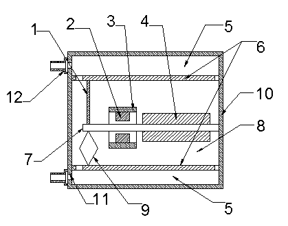
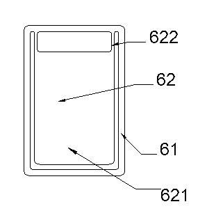
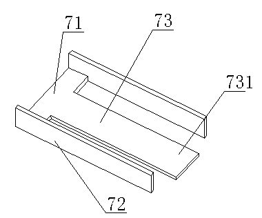
[0029] Such as Figure 1-3 As shown, a receiver with an improved transmission mechanism includes an electromagnetic shielding case 10, a diaphragm 6, an electromagnetic conversion mechanism and a power transmission mechanism, and the diaphragm 6 and the electromagnetic conversion mechanism are all arranged in the electromagnetic shielding case 10; wherein the electromagnetic conversion The mechanism includes an armature 7, and the diaphragm 6 is symmetrically arranged on the upper and lower sides of the electromagnetic conversion mechanism along the vibration direction of the armature 7, and is connected to the armature 7 through a power transmission mechanism. The power transmission mechanism includes a conductive rod 1 and a conductive ring 9. The diaphragm 6 on one side of the armature 7 is connected to the armature 7 through the conductive rod 1, and the diaphragm 6 on the other side of the armature 7 is connected to the armature 7 through the conductive ring 9. The armatu...

Embodiment 2

[0035] All the other are identical with embodiment 1, and difference is, as Figure 4As shown, the material of the conduction ring 9 is stainless steel, the conduction ring 9 is a circular ring, the armature 7 and the diaphragm 6 are fixedly connected to the axisymmetric ends of the circular ring respectively, and the conduction rod 1 and the armature 7 and the diaphragm 6 are fixedly connected. The connection is welding, and the connection between the conductive ring 9 and the armature 7 and the diaphragm 6 is also welding.

Embodiment 3

[0037] All the other are identical with embodiment 2, and difference is, as Figure 5 As shown, the conductive ring is an elliptical ring, and the armature 7 and the vibrating membrane 6 are fixedly connected to both ends of the major axis or both ends of the short axis of the elliptical ring, respectively.


PUM


Abstract

A telephone receiver with an improved transmission mechanism comprises an electromagnetic shielding housing, vibrating membranes, an electromagnetic conversion mechanism and a power transmission mechanism, wherein the vibrating membranes and the electromagnetic conversion mechanism are arranged in the electromagnetic shielding housing; the electromagnetic conversion mechanism comprises an armature; and the vibrating membranes are symmetrically arranged on the upper and lower sides of the electromagnetic conversion mechanism in a vibrating direction of the armature, and connected with the armature in a drive manner by the power transmission mechanism. According to the telephone receiver with the improved transmission mechanism, the special transmission mechanism is adopted to transmit vibrating output of the electromagnetic conversion mechanism to the vibrating membranes, so that audio output of the telephone receiver is doubled; and the axial vibration of a telephone receiver housing is offset due to opposite movement between the vibrating membranes.

Description

technical field [0001] The invention relates to an electroacoustic conversion device, in particular to a receiver with an improved conduction mechanism. Background technique [0002] Receivers using moving iron units have been more and more used in various fields of people. With the improvement of people's quality of life, the volume requirements of receivers are becoming smaller and smaller, and the requirements for voice quality of receivers are also increasing. However, with the miniaturization of the moving iron unit in the receiver, the electro-acoustic conversion efficiency of the moving iron unit will also decrease. In order to obtain better voice quality, the form of multi-unit combination is currently used to meet the requirements, but it will come The only disadvantages are the increase in production cost and the increase in the size of the receiver. At the same time, the axial vibration of the receiver shell due to the vibration of the diaphragm will cause t...

Claims


Application Information

Patent Timeline
IPC IPC(8): H04R9/08H04R9/02
CPCH04R11/06H04R1/023
Inventor 梁皖渝张秀梅
Owner SUZHOU YICHUAN TECH CO LTD
Features
  • R&D
  • Intellectual Property
  • Life Sciences
  • Materials
  • Tech Scout
  • Unparalleled Data Quality
  • Higher Quality Content
  • 60% Fewer Hallucinations
Learn More