Micro part clamping device

A technology of tiny parts and parts clamps, applied in workpiece clamping devices, manufacturing tools, etc., can solve the problems of assembly difficulty and damage

Inactive Publication Date: 2013-08-07
DALIAN UNIV OF TECH
View PDF5 Cites 18 Cited by
  • Summary
  • Abstract
  • Description
  • Claims
  • Application Information

AI Technical Summary

Problems solved by technology

[0002] With the miniaturization of parts and the improvement of assembly precision requirements, the difficulty of assembly is also increasing. However, when using existing fixtures to clamp and position parts, it is easy to cause excessive warping of the workpiece during the press-fitting process. deformed, or even damaged

Method used


Image

  • Micro part clamping device
  • Micro part clamping device
  • Micro part clamping device

Examples


Embodiment Construction

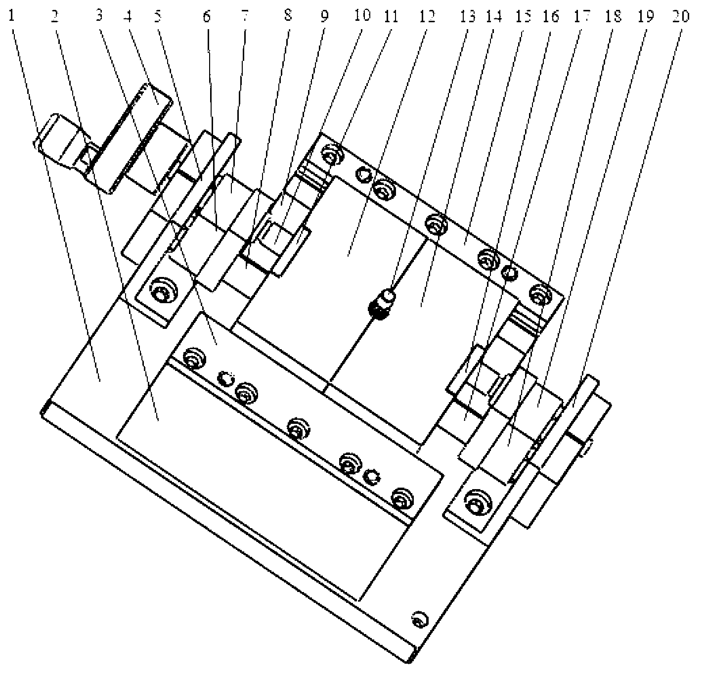
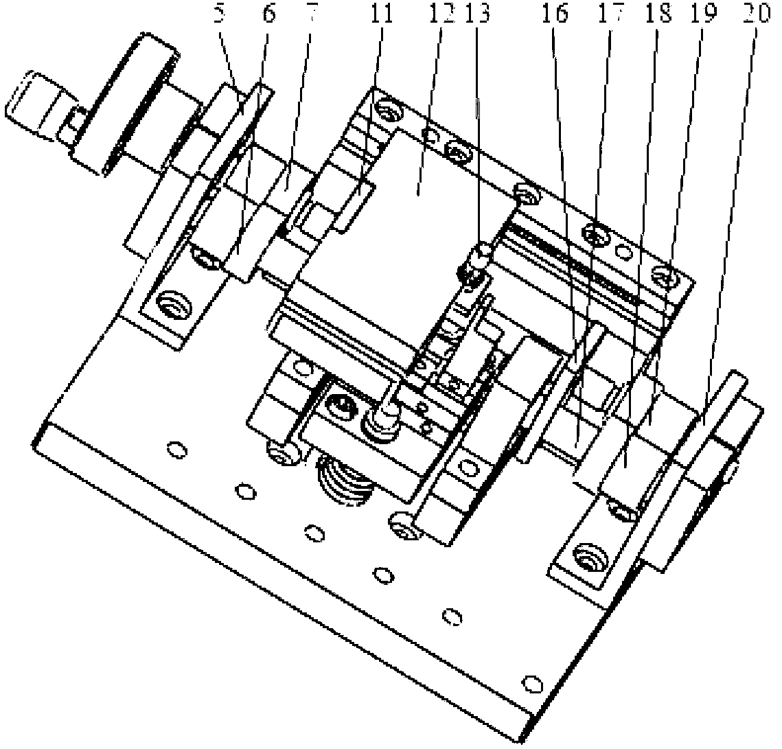
[0019] Left support 2, right support 9 and bearing support seat one 5 and bearing support seat two 20 are installed on the fixture installation base 1, and left cross plate 12 and right cross plate 14 are installed on the guide rail surface of left support 2 and right support 9.

[0020] By turning the hand wheel 4, the transmission shaft 10 is rotated, and the transmission shaft 10 transmits the motion to the screw rod 18 through the meshing of the gear 2 7 and the gear 1 6, and the screw rod 1 8 drives the stopper 11 through threaded cooperation, and the stopper 11 drives The left horizontal plate 12 fixed together with it moves; while the left horizontal plate moves, the drive shaft 10 transmits the motion to the screw 2 17 through the meshing of the gear 3 18 and the gear 4 19, and the screw 2 17 drives the stopper 2 through thread cooperation 16, stop block two 16 drives the right cross plate 14 movement that is fixed together with it, so just realized left cross plate 12 ...


PUM


Abstract

The invention belongs to the field of clamp design and relates to a micro part clamping device. The micro part clamping device comprises a transmission mechanism, a clamping mechanism, a left press plate, a right support, a left transverse plate, a micro part, a right transverse plate, a right press plate, a third gear, a fourth gear and a clamp installing base. The left transverse plate and the right transverse plate are opened towards two sides by adjusting hand wheels, and the micro part is placed on the left transverse plate or the right transverse plate to enable the left transverse plate and the right transverse plate to be closed so as to finish micro part installation. A pneumatic gripper moves to enable a clamping finger fixing seat fixed on the pneumatic gripper to finish micro part clamping. When the micro part is pressed in the pressing process, the clamping finger fixing seat vertically floats in the pressing direction within a small range with the micro part, accordingly a phenomenon that the clamped micro part is beyond of a positioning position is avoided, and clamping and positioning of the micro part is achieved.

Description

technical field [0001] The invention relates to a clamping device for tiny parts, aiming at preventing over-positioning of the tiny parts during the pressing process. Background technique [0002] With the miniaturization of parts and the improvement of assembly precision requirements, the difficulty of assembly is also increasing. However, when using existing fixtures to clamp and position parts, it is easy to cause excessive warping of the workpiece during the press-fitting process. deformed or even damaged. [0003] In order to solve the above problems, the industry has invented a new type of clamping device to replace the clamping and positioning of a tiny part in the press-fitting process of the existing clamps. This new clamping mechanism can realize the axial movement of the clamp and tiny parts within a certain range during the press-fitting process through the two springs under the cylinder support inside the clamp, preventing excessive positioning of the parts due...

Claims


Application Information

Patent Timeline
Patent Type & Authority Applications(China)
IPC IPC(8): B25B11/00
Inventor 娄志峰王晓东由博罗怡刘西风
Owner DALIAN UNIV OF TECH
Why Eureka
Try Eureka