Built-in ventilation pneumatic pump

A built-in, pneumatic pump technology, used in pumps, piston pumps, machines/engines, etc., can solve the problems of large overall structure, large wear, and high noise, and achieve smooth and efficient movement, convenient passage, and low noise.

Inactive Publication Date: 2013-08-07
NINGBO UNIV
View PDF6 Cites 0 Cited by
  • Summary
  • Abstract
  • Description
  • Claims
  • Application Information

AI Technical Summary

Problems solved by technology

[0003] A pneumatic pump disclosed in Chinese utility model patent ZL200820164523.X includes a cylinder and a reversing mechanism. The reversing mechanism includes a valve seat, a reversing rod, a reversing slider, a reversing slip ring, a valve seat, and There are three horizontally arranged windows on the wall, the middle window communicates with the air inlet on the valve seat, and the two windows at both ends communicate with the upper chamber and the lower chamber; the reversing slip ring is embedded in the reversing slider facing the window On the side wall of the reversing slip ring, the center of the reversing slip ring is pierced with a pressure spring with two ends respectively against the reversing slider and the inner wall of the reversing slip ring to make the reversing slip ring close to the side wall of the valve seat; the top of the reversing rod and the reversing slip ring When the piston rod moves, it can push the reversing slider to slide horizontally. There is a return spring between the reversing slider and the valve seat to make the reversing slider move horizontally and reset; Disadvantages such as high wear and noise, and its overall structure is relatively large

Method used


Image

  • Built-in ventilation pneumatic pump
  • Built-in ventilation pneumatic pump
  • Built-in ventilation pneumatic pump

Examples


Embodiment Construction

[0020] The present invention will be further described in detail below in conjunction with the accompanying drawings and embodiments.

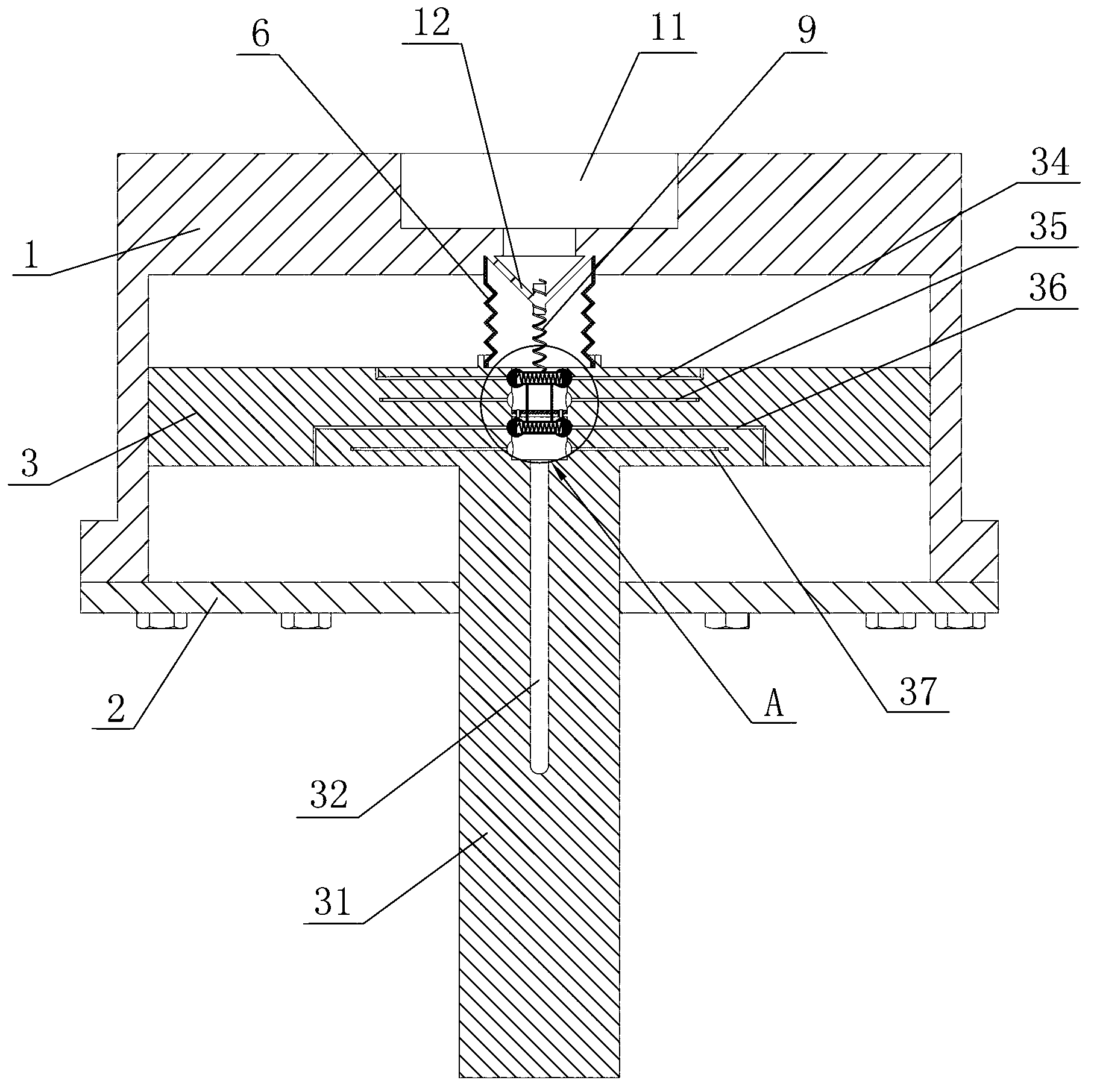
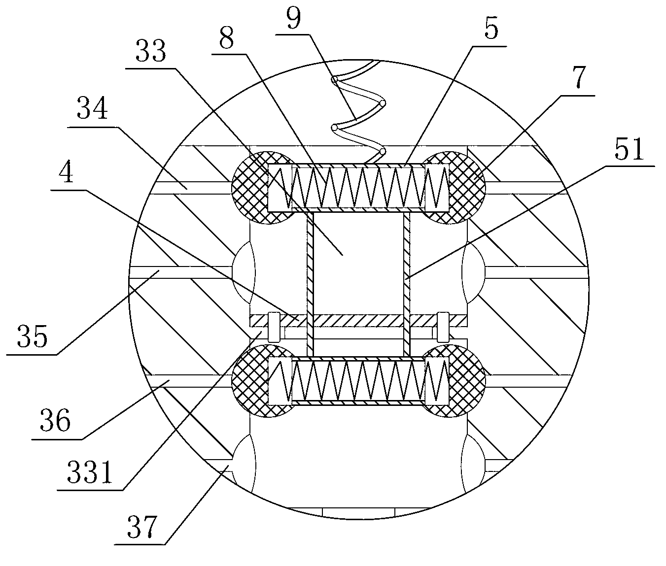
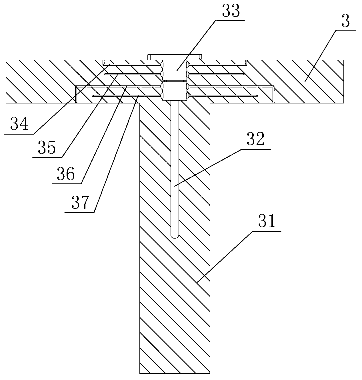
[0021] As shown in the figure, the built-in ventilation pneumatic pump includes a cylinder body 1, a bottom cover 2 and a piston 3, the bottom cover 2 is sealed and fixedly connected with the cylinder body 1, the piston 3 is sealed and slidably arranged in the cylinder body 1, and the piston 3 is integrated A piston rod 31 is provided, and the piston rod 31 seals and passes through the bottom cover 2. The cylinder body 1 is provided with an air inlet 11, and the piston rod 31 is provided with an exhaust passage 32 communicating with the outside world. The piston 3 is provided with a gas reversing Mechanism, the gas reversing mechanism includes a partition 4 and two connecting pipes 5 arranged in parallel up and down, the partition 4 is located between the two connecting pipes 5, and the two connecting pipes 5 are fixedly connected by a connecti...


PUM


Abstract

The invention discloses a built-in ventilation pneumatic pump which comprises a cylinder, a bottom cover and a piston, wherein the bottom cover is fixedly connected with the cylinder in a sealing mode, the piston is slidingly arranged in the cylinder in a sealing mode, a piston rod is fixedly arranged on the piston, and the piston rod penetrates through the bottom cover in a sealing mode. The built-in ventilation pneumatic pump is characterized in that an air inlet is arranged on the cylinder, an air outlet channel which is communicated with the outside is arranged on the piston rod, an air reversing mechanism is arranged in the piston, and the cylinder is provided with a driving mechanism for driving the air reversing mechanism to move vertically. The built-in ventilation pneumatic pump has the advantages that the air reversing mechanism is arranged in the piston, and the ventilation way of the piston is transferred to be carried out in the piston, so that the normal operation of the original piston and the smooth and efficient movement are ensured simultaneously, the noise is very low in the working process, and the utilization value of the piston is improved to provide a convenient channel for the ventilation and enable the pneumatic pump to have a compact structure.

Description

technical field [0001] The invention relates to a pneumatic pump, in particular to a built-in ventilation pneumatic pump. Background technique [0002] The pneumatic pump uses compressed gas as the power source, and controls the flow direction of the compressed gas through the gas distribution and reversing device. The compressed gas drives the cylinder piston to move, and realizes the function of outputting reciprocating linear motion. At present, the pneumatic pump is often used as a power source for high-pressure airless spraying machines, etc. . [0003] A pneumatic pump disclosed in Chinese utility model patent ZL200820164523.X includes a cylinder and a reversing mechanism. The reversing mechanism includes a valve seat, a reversing rod, a reversing slider, a reversing slip ring, a valve seat, and There are three horizontally arranged windows on the wall, the middle window communicates with the air inlet on the valve seat, and the two windows at both ends communicate w...

Claims


Application Information

Patent Timeline
Patent Type & Authority Applications(China)
IPC IPC(8): F04B35/02
Inventor 马志勇陈宗威
Owner NINGBO UNIV
Why Eureka
Try Eureka