
Array substrate, manufacturing method thereof and display device

A technology of array substrate and manufacturing method, which is applied in the field of liquid crystal display, can solve problems such as large contact resistance and uneven charge distribution, and achieve the effect of uniform charge distribution

Active Publication Date: 2013-08-07
HEFEI BOE OPTOELECTRONICS TECH +1
View PDF6 Cites 7 Cited by
  • Summary
  • Abstract
  • Description
  • Claims
  • Application Information

AI Technical Summary

Problems solved by technology

However, when the metal in the via hole is in contact with the pixel electrode, a large contact resistance will be generated, resulting in uneven charge distribution between the common electrode and the pixel electrode

Method used


Image

  • Array substrate, manufacturing method thereof and display device
  • Array substrate, manufacturing method thereof and display device
  • Array substrate, manufacturing method thereof and display device

Examples


Embodiment approach

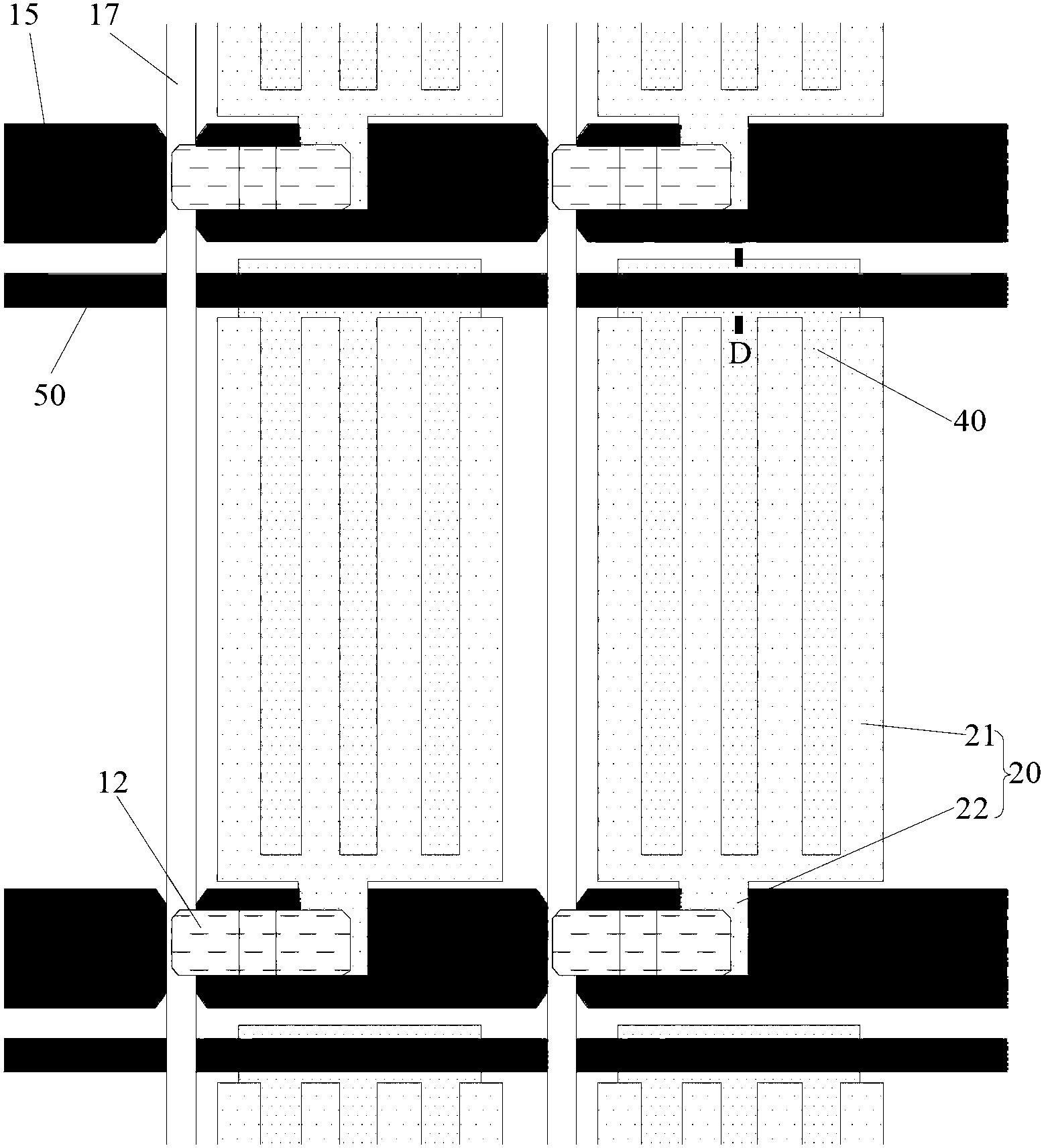
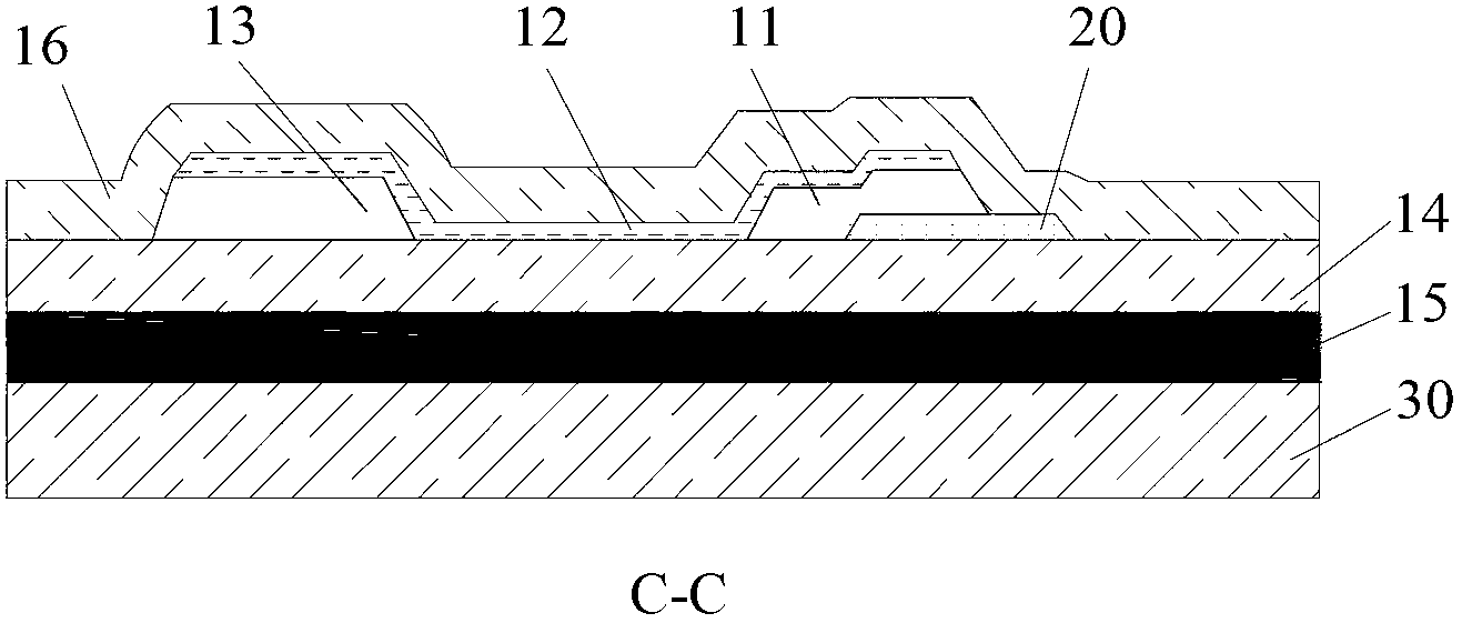
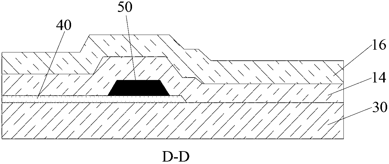
[0066] As the first embodiment of the present invention, such as figure 1 with figure 2 As shown, the pixel electrode 20 may include a pixel electrode body 21 and a connecting portion 22 protruding from the pixel electrode body 21. The connecting portion 22 is disposed between the drain electrode 11 of the thin film transistor and the gate insulating layer 14 of the thin film transistor. between. able to pass Figure 8 The processing steps shown in FIG. 2 form the pixel electrode 20 in this manner. Hereinafter, the manufacturing method of the array substrate described in the first embodiment will be introduced in detail, which will not be repeated here.

[0067] As the second embodiment of the present invention, such as Picture 9 with Picture 10 As shown, the pixel electrode 20 includes a pixel electrode body 21 and a connecting portion 22 protruding from the pixel electrode body 21, and the connecting portion 22 covers a part of the upper surface of the drain electrode 11 of ...


PUM


Abstract

The invention discloses an array substrate. The array substrate comprises a display area and a peripheral area adjacent to the display area. The display area comprises a plurality of pixel units. A thin film transistor and a pixel electrode are arranged in each pixel unit. Drain electrodes of the thin film transistors are contacted with the pixel electrodes directly. The invention further discloses a display device comprising the array substrate and a manufacturing method of the array substrate. In the array substrate, the pixel electrodes are contacted with the thin film transistors directly, so that contact resistance can not be caused, and an electric field between a public electrode and the pixel electrodes can be distributed evenly.

Description

Technical field [0001] The present invention relates to liquid crystal display technology, in particular to an array substrate, a manufacturing method of the array substrate, and a display device including the array substrate. Background technique [0002] The array substrate is divided into a display area and a peripheral area adjacent to the display area. The display area is divided into a plurality of pixel units. Each pixel unit is provided with a thin film transistor and a pixel electrode. In the pixel unit, the drain of the thin film transistor and the pixel electrode are electrically connected through a via hole. However, when the metal in the via hole is in contact with the pixel electrode, a larger contact resistance will be generated, resulting in uneven charge distribution between the common electrode and the pixel electrode. [0003] Therefore, how to make the charge uniformly distributed between the common electrode and the pixel electrode becomes a technical problem ...

Claims


Application Information

Patent Timeline
Patent Type & Authority Applications(China)
IPC IPC(8): G02F1/1362G02F1/1343H01L21/77
CPCG02F1/1368G02F1/133707H01L27/124H01L27/1225H01L27/127H01L27/1296G02F1/134372G02F1/136295H10K59/123
Inventor 徐向阳聂竹华邓立赟金玟秀王凯
Owner HEFEI BOE OPTOELECTRONICS TECH
Learn More