Novel power transfer device for switchgear

A technology of power transmission device and switchgear, which is applied in substation/switch layout details, electrical components, etc., can solve the problems of poor synchronization of power transmission, can not fully guarantee the synchronization of three-phase power on and off of switchgear, etc., to ensure synchronization The effect of passing

Inactive Publication Date: 2013-08-07
SUZHOU LONGER ELECTRIC CO LTD
View PDF4 Cites 0 Cited by
  • Summary
  • Abstract
  • Description
  • Claims
  • Application Information

AI Technical Summary

Problems solved by technology

Power transmission devices are all arranged in the switchgear, and the power transmission devices of the prior art, such as the attached figure 1 As shown, it includes a power arm female head 1, a power arm male head 2, and a hexagonal shaft 4; the heads of the power arm female head 1 and the power arm male head 2 are connected by a connecting shaft 3; the power arm female head 1, The tail of the power arm male head 2 is respectively provided with hexagonal through holes (not shown); the hexagonal shaft 4 passes through the hexagonal through holes of the power arm female head 1 and the power arm male head 1 respectively, so that the power arm female head 1. The male head 1 of the power arm is connected together; the power transmission device of this structure has a gap between the hexagonal shaft 4 and the hexagonal through hole at the tail of the female head 1 of the power arm and the male head 1 of the power arm, so that the power transmission is synchronized It is poor, and cannot fully guarantee the synchronization of the three-phase power on and off of the switchgear, so that the corresponding position can only be guaranteed by changing the corresponding position under the premise of different phases in the test.

Method used


Image

  • Novel power transfer device for switchgear
  • Novel power transfer device for switchgear
  • Novel power transfer device for switchgear

Examples


Embodiment Construction

[0016] The present invention will be further described in detail below in conjunction with the accompanying drawings and specific embodiments.

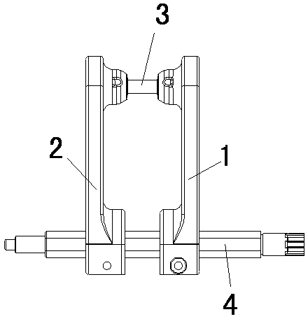
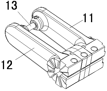
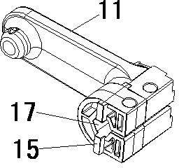
[0017] attached Figure 2-4 It is a power transmission device for a new type of switchgear according to the present invention, including a power arm female head 11, a power arm male head 12, and a hexagonal shaft (not shown); the power arm female head 11, power arm male head The head of 12 is connected by a connecting shaft 13; the side of the tail of the power arm female head 11 is provided with a convex strip 15; the tail of the power arm male head 12 is provided with a convex strip 15 corresponding side Groove 16; the convex strip 15 is inserted into the groove 16; the tail of the power arm female head 11 is provided with a first hexagonal through hole 17, and the tail of the power arm male head 12 is provided with a second hexagonal through hole 18 The hexagonal shaft passes through the first hexagonal through hole 17 and the sec...


PUM


Abstract

The invention discloses a novel power transfer device for switchgear. The power transfer device comprises a power arm female head, a power arm male head and a hexagonal shaft, wherein the head parts of the power arm female head and the power arm male head are connected through a connecting shaft; the side part of the tail part of the power arm female head is provided with a convex strip; the side part of the tail part of the power arm male head corresponding to the convex strip is provided with a groove; the convex strip is inserted into the groove; the tail part of the power arm female head is provided with a first hexagonal through hole, and the tail part of the power arm male head is provided with a second hexagonal through hole; and the hexagonal shaft penetrates through the first hexagonal through hole and the second hexagonal through hole respectively, so that the power arm female head and the power arm male head are connected together. According to the power transfer device for switchgear, the tail parts of the power arm female head and the power arm male head are also connected into a whole body through matching of the convex strip and the groove; and thus, synchronous transfer of power can be guaranteed.

Description

technical field [0001] The invention relates to an improvement of a power transmission device, in particular to a new type of power transmission device for switchgear with good power synchronous transmission performance. Background technique [0002] Switchgear is a general term for high-voltage distribution cabinets, generators, transformers, power lines, circuit breakers, low-voltage switch cabinets, switchboards, switch boxes, control boxes and other power distribution equipment in the power system. Power transmission devices are all arranged in the switchgear, and the power transmission devices of the prior art, such as the attached figure 1 As shown, it includes a power arm female head 1, a power arm male head 2, and a hexagonal shaft 4; the heads of the power arm female head 1 and the power arm male head 2 are connected by a connecting shaft 3; the power arm female head 1, The tail of the power arm male head 2 is respectively provided with hexagonal through holes (not...

Claims


Application Information

Patent Timeline
Patent Type & Authority Applications(China)
IPC IPC(8): H02B1/00
Inventor 袁忠王庆
Owner SUZHOU LONGER ELECTRIC CO LTD
Why Eureka
Try Eureka