Trigger method of linear scanning industrial camera with filter function based on ISA (industry standard architecture) bus

A line scan and industrial camera technology, applied to color TV parts, TV system parts, TVs, etc., can solve the problems of not being able to guarantee the mechanical beam, not being able to trigger the camera once, etc.

Active Publication Date: 2013-08-07
宁波智能装备研究院有限公司
View PDF3 Cites 3 Cited by
  • Summary
  • Abstract
  • Description
  • Claims
  • Application Information

AI Technical Summary

Problems solved by technology

[0003] In order to solve the problem in the existing triggering method that the camera cannot be triggered every time the camera moves 25um, and it cannot be guaranteed that the mechanical crossbeam only triggers the camera when it move

Method used


Image

  • Trigger method of linear scanning industrial camera with filter function based on ISA (industry standard architecture) bus
  • Trigger method of linear scanning industrial camera with filter function based on ISA (industry standard architecture) bus
  • Trigger method of linear scanning industrial camera with filter function based on ISA (industry standard architecture) bus

Examples


specific Embodiment approach 1

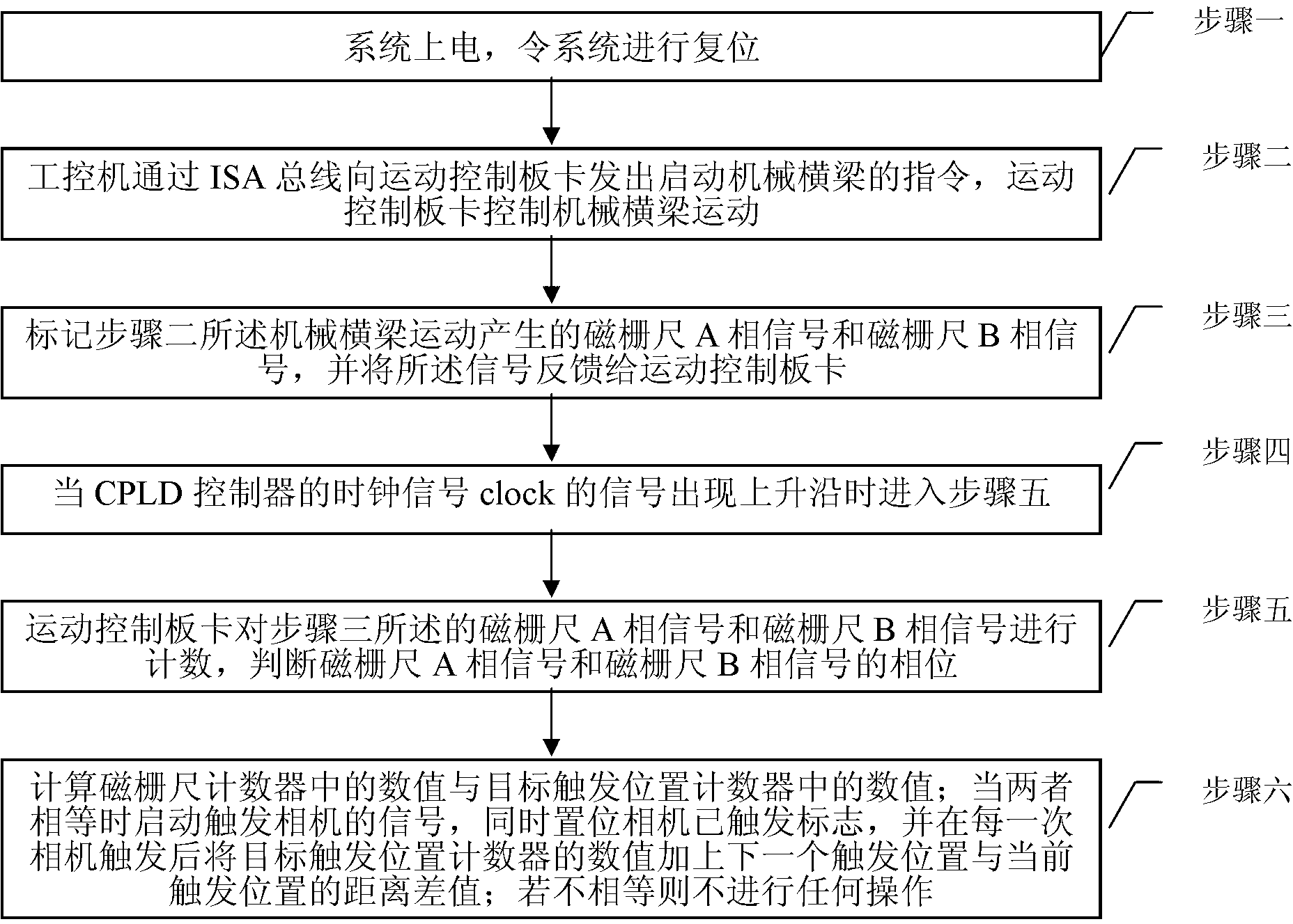
[0020] Specific implementation mode 1. Combination figure 1 This specific embodiment will be described. A method for triggering a line scan industrial camera with a filtering function based on an ISA bus, comprising the following steps:

[0021] Step 1: Power on the system to reset the system;

[0022] The reset is to use the CPLD controller on the motion control board to initialize the magnetic scale pulse number counter, the magnetic scale A phase signal shift counter, the magnetic scale B phase signal shift counter, the target trigger position counter and the trigger signal width counter;

[0023] Step 2: The industrial computer sends an instruction to start the mechanical crossbeam to the motion control board through the ISA bus, and the motion control board controls the movement of the mechanical crossbeam;

[0024] Step 3: mark the magnetic scale A phase signal and the magnetic scale B phase signal generated by the mechanical beam movement in step 2, and feed back the...

specific Embodiment approach 2

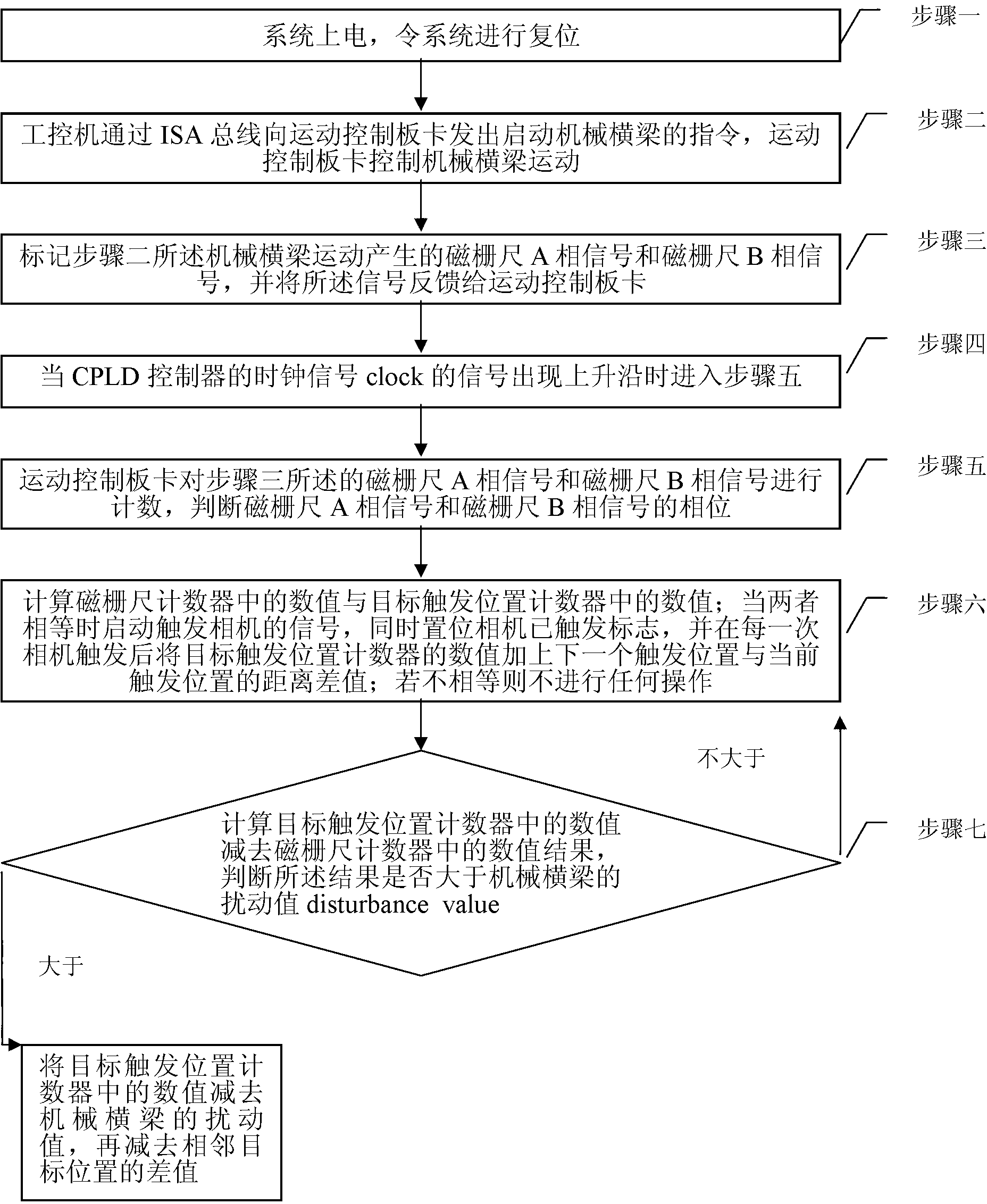
[0031] Specific Embodiment 2. The difference between this specific embodiment and specific embodiment 1 is that after starting the trigger camera signal in step 6, step 7 is also included: calculating the value in the target trigger position counter minus the value in the magnetic scale counter As a result, it is judged whether the result is greater than the disturbance value disturbance_value of the mechanical beam;

[0032] If it is not greater than the disturbance value disturbance_value of the mechanical beam, return to step 6;

[0033] If it is greater than the disturbance value disturbance_value of the mechanical beam, subtract the value in the target trigger position counter from the disturbance value disturbance_value of the mechanical beam, and then subtract the difference between adjacent target positions.

[0034] The target position is the trigger position (the position where the camera needs to be triggered when the camera moves here). There are a series of trigge...

specific Embodiment approach 3

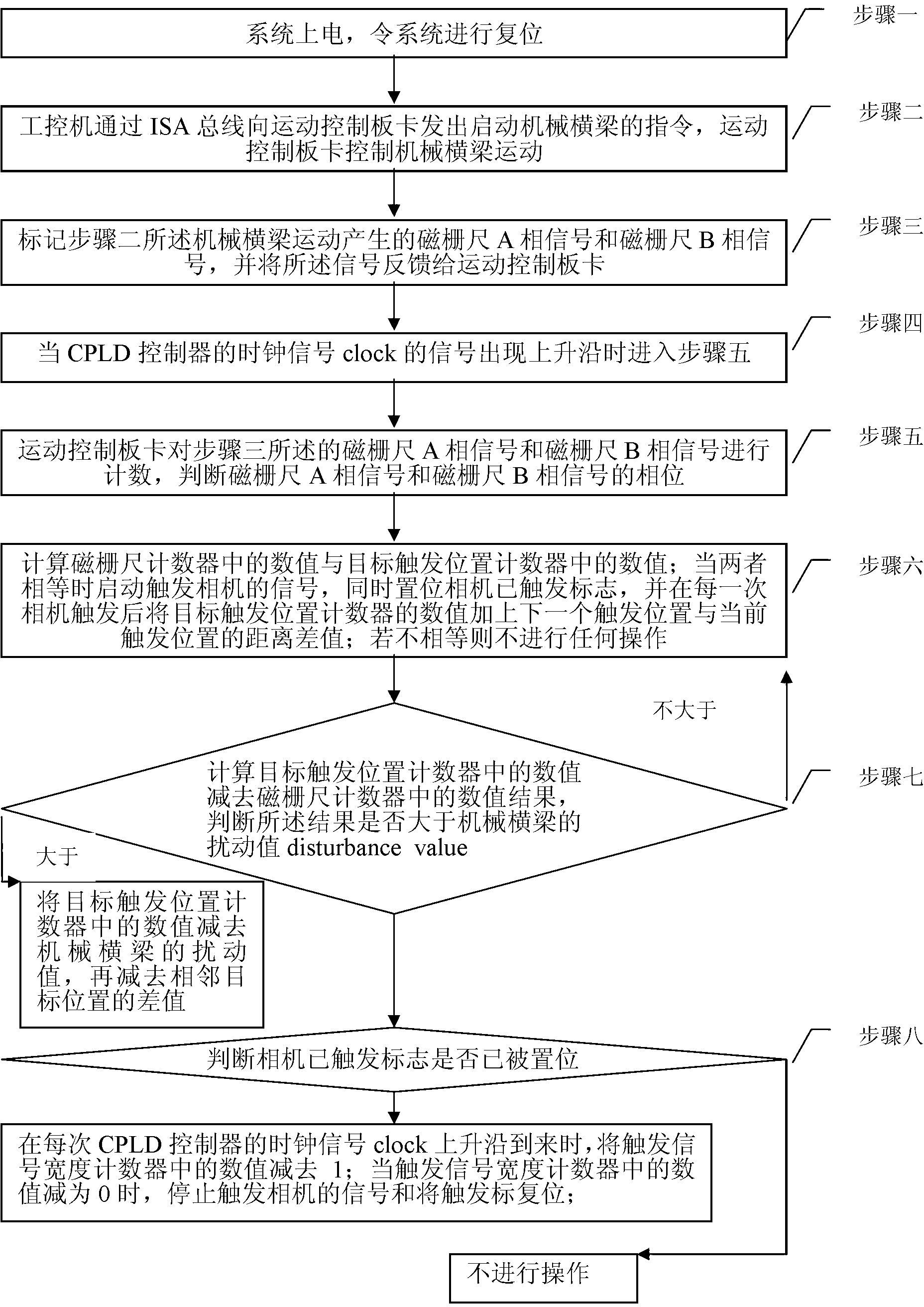
[0038] Embodiment 3. This embodiment is different from Embodiment 2 in that step 7 includes step 8 after subtracting the difference between adjacent target positions: judging whether the camera has triggered the flag camera_flag to be set;

[0039] If it has been set, when the rising edge of the clock signal clock of the CPLD controller arrives, the value in the trigger signal width counter is subtracted by 1;

[0040] When the value in the trigger signal width counter is reduced to 0, stop triggering the camera signal camera_line and reset the trigger flag camera_flag;

[0041] If not set, no operation is performed.

[0042] This step makes the width of the signal camera_line that triggers the camera equal to the period of the trigger signal width counter multiplied by the CPLD clock signal clock. By changing the value in the trigger signal width counter, the width of the signal camera_line that triggers the camera can be set arbitrarily. Only by using this specific implemen...


PUM


Abstract

The invention relates to a linear scanning industrial camera trigger method, and particularly relates to a trigger method of a linear scanning industrial camera with filter function based on an ISA (industry standard architecture) bus, which solves the problem that the camera can not be triggered once the camera moves 25 microns, and the condition that the camera is triggered when a mechanical crossbeam moves to a target position in only one direction and is not triggered during reverse direction movement of the mechanical crossbeam can not be ensured in existing trigger method. The trigger method comprises the following steps: a system is electrified to be reset; an industrial computer transmits an instruction for starting the mechanical crossbeam to a motion control board card through the ISA bus, and the motion control board card controls the mechanical crossbeam to move; A phase signals and B phase signals of a magnetic grating ruler are labeled, and the signals are fed back to the motion control board card; and judging the phase, and calculating the number in a magnetic grating ruler counter and the number in a target trigger position counter. The trigger method provided by the invention can be widely used in the linear scanning industrial camera trigger process.

Description

technical field [0001] The invention relates to a trigger method for a line scan industrial camera. Background technique [0002] Line scan industrial cameras are a category of visual industrial cameras with high resolution, suitable for high-precision measurement occasions, and can accurately measure to microns. Due to the high-precision characteristics of the camera, the camera is required to be triggered every 25um, but in the existing trigger method, the camera cannot be triggered every 25um, and there is no guarantee that the mechanical beam will only trigger the camera when it moves to the target position in one direction. , the reverse movement does not trigger the camera. Contents of the invention [0003] In order to solve the problem in the existing triggering method that the camera cannot be triggered every time the camera moves 25um, and it cannot be guaranteed that the mechanical crossbeam only triggers the camera when it moves to the target position in one d...

Claims


Application Information

Patent Timeline
IPC IPC(8): H04N5/232
Inventor 高会军徐世东任雨张增杰谢文麟
Owner 宁波智能装备研究院有限公司
Why Eureka
Try Eureka