Die and method for rolling tubeless rim plate

A sheet and rim technology is applied in the field of tubeless rim sheet rolling die and rolling to achieve the effects of improving rolling efficiency, increasing bearing capacity and metal utilization rate, and reducing rolling process

Inactive Publication Date: 2013-08-14
李昕远
View PDF8 Cites 8 Cited by
  • Summary
  • Abstract
  • Description
  • Claims
  • Application Information

AI Technical Summary

Problems solved by technology

[0003] The purpose of the present invention is to provide a tubeless rim plate rolling die and rolling method to solve the internal defects such as looseness and shrinkage cavity of the metal on the edge of the tubeless rim plate and improve the rolling efficiency

Method used


Image

  • Die and method for rolling tubeless rim plate
  • Die and method for rolling tubeless rim plate
  • Die and method for rolling tubeless rim plate

Examples


Embodiment Construction

[0017] The present invention will be described in further detail below in conjunction with the accompanying drawings.

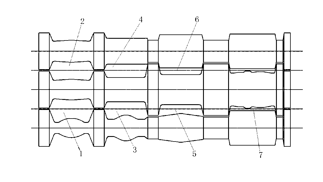
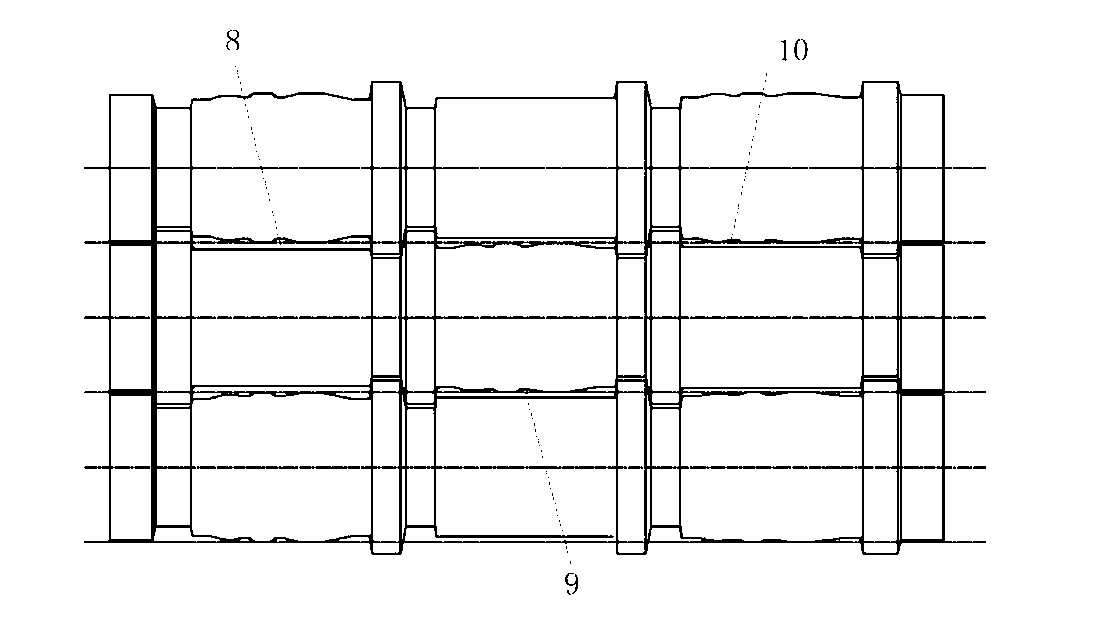
[0018] Such as Figure 2-5 As shown, the tubeless rim plate rolling die of the present invention includes multiple stages of rolls, and the multiple stages of rolls are respectively provided with different-shaped passes.

[0019] In the embodiment, there are 4 shifts of the rolls, 12 passes of the pass, and one pass for each pass. The pass includes the first pass type 1, the second pass type 2, the third pass type 3, the fourth pass type 4, the fifth pass type 5, the sixth pass type 6, the seventh pass type 7, and the eighth pass type 8 , the ninth hole type 9, the tenth hole type 10, the eleventh hole type 11 and the twelfth hole type 12; the size of the hole type between the first hole type 1 to the twelfth hole type 12 gradually decrease.

[0020] The middle part of the first pass type 1, the second pass type 2, the third pass type 3 and the ...


PUM


Abstract

The invention discloses a die and a method for rolling a tubeless rim plate. The die comprises a plurality of rolls and is characterized in that the plurality of rolls are provided with hole patterns in different shapes respectively. During rolling of the tubeless rim plate, high-temperature billets are sequentially fed into rolls with hole pattern structures in different shapes to finish rolling of the tubeless rim plate. According to the die and the method, the plurality of rolls are provided with the hole patterns in different shapes, a multi-rolling mode is adopted, the problems that shapes of finished plate edges are out of control, and internal defects, such as looseness and shrinkage in metal of plate edges during rolling by existing rolls are solved, the bearing capacity of wheels and the metal utilization rate are improved, edges of wheels cannot deform easily, rolling processes are reduced, and the rolling efficiency is improved.

Description

technical field [0001] The invention relates to a rolling die and a rolling method for a tubeless rim plate. Background technique [0002] As shown in Figure 1, the production of traditional tubeless rim plates is rolled by strip rolling mills, which are basically flat roll rolling—that is, non-hole rolling. The metal is free and wide, and there is no lateral pressure on both sides of the material. After several passes of rolling, the edge shape of the finished plate cannot be controlled, and the metal on the edge of the plate has internal defects such as looseness and shrinkage cavity. The metal on both sides must be cut off during wheel production. , otherwise the produced wheels have a small bearing capacity, resulting in less vehicle load capacity, easy deformation and air leakage at the edge of the wheel, affecting the safety of the vehicle, and low rolling efficiency and metal utilization. Contents of the invention [0003] The purpose of the present invention is to...

Claims


Application Information

Patent Timeline
Patent Type & Authority Applications(China)
IPC IPC(8): B21H8/02
Inventor 吴晓山
Owner 李昕远
Why Eureka
Try Eureka