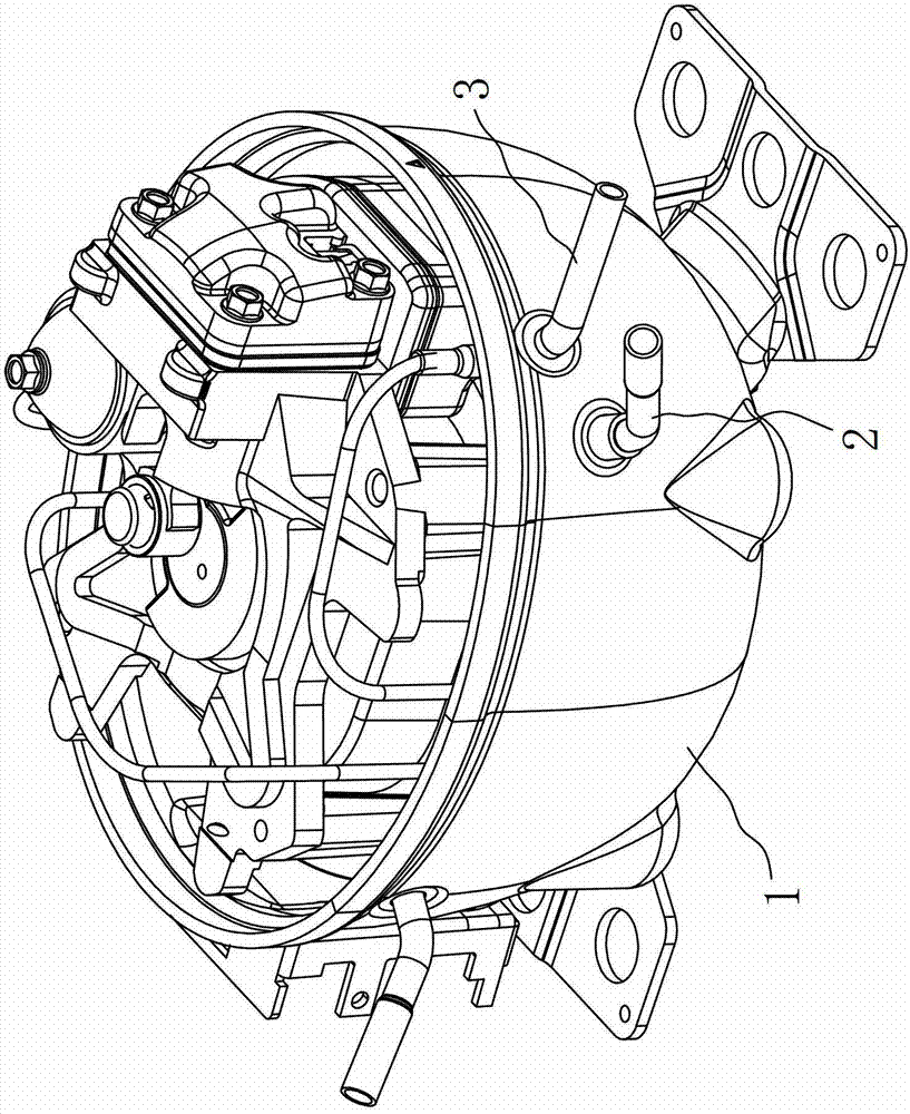
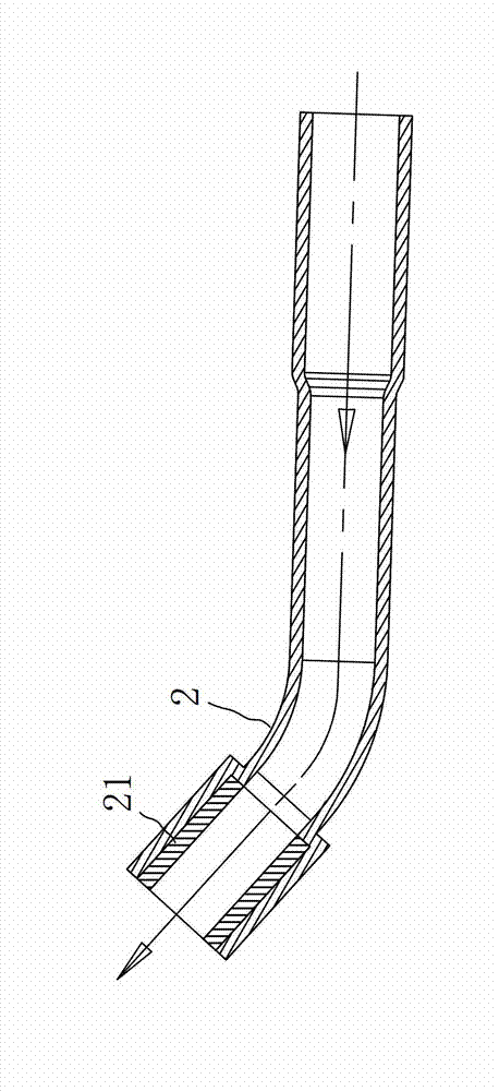
Refrigerating compressor with adiabatic air suction tube

A technology for a refrigeration compressor and a suction pipe, applied in the field of refrigeration compressors, can solve the problems of reducing the refrigeration capacity of the compressor, affecting the refrigeration efficiency of the compressor, detrimental to the performance of the product, etc., and achieving the effect of improving the refrigeration efficiency.

Inactive Publication Date: 2013-08-14
WANBAO GROUP COMPRESSOR CO LTD
View PDF7 Cites 3 Cited by
  • Summary
  • Abstract
  • Description
  • Claims
  • Application Information

AI Technical Summary

Problems solved by technology

Therefore, the temperature of the high-temperature casing and exhaust pipe will be transferred to the suction pipe, which will heat up the low-temperature suction gas and reduce the cooling capacity of the compressor, thereby affecting the cooling efficiency of the compressor.
Not conducive to the further improvement of product performance

Method used


Image

  • Refrigerating compressor with adiabatic air suction tube
  • Refrigerating compressor with adiabatic air suction tube

Examples


Embodiment Construction

[0014] The concept, specific structure and technical effects of the present invention will be clearly and completely described below in conjunction with the embodiments and accompanying drawings, so as to fully understand the purpose, features and effects of the present invention. Apparently, the described embodiments are only some of the embodiments of the present invention, rather than all of them. Based on the embodiments of the present invention, other embodiments obtained by those skilled in the art without creative efforts belong to The protection scope of the present invention. In addition, all the connection / connection relationships mentioned in this article do not refer to the direct connection of components, but mean that a better connection structure can be formed by adding or reducing connection accessories according to specific implementation conditions. The various technical features in the invention can be combined interactively on the premise of not conflicting...


PUM


Abstract

The invention discloses a refrigerating compressor with an adiabatic air suction tube. The refrigerating compressor comprises a case provided with an air suction tube joint and an air discharge tube joint. Outside the case, the end of the air suction tube is communicated with the air suction tube joint, the end of an air discharge tube is communicated with the air discharge tube joint, and the air suction tube further comprises an adiabatic layer located on the inner wall of the end of the air suction tube. The adiabatic layer is arranged on the inner wall of the end of the air suction tube, outside heat can be prevented from transmitting to original air inside the air suction tube and especially adjacent to the air suction tube joint, low temperature of suction air is guaranteed, and refrigerating efficiency is improved. The refrigerating compressor is adaptable to various places requiring refrigeration.

Description

technical field [0001] The invention relates to a refrigeration compressor, in particular to a refrigerator refrigeration compressor. Background technique [0002] The refrigeration compressor includes a closed casing and core components in the casing, and the casing is provided with a suction pipe interface and an exhaust pipe interface. The suction pipe and the exhaust pipe are outside the casing, and are respectively connected to the suction pipe interface and the exhaust pipe interface, so that they are connected to the suction hole and the exhaust hole of the cylinder assembly of the movement after passing through the casing. . When the compressor is working, the low-temperature gas is sucked into the machine from the suction pipe, and after being compressed, it becomes high-temperature and high-pressure refrigerant and is discharged from the discharge pipe. [0003] The efficiency of the compressor is closely related to the suction and discharge temperature. Usually,...

Claims


Application Information

Patent Timeline
Patent Type & Authority Applications(China)
IPC IPC(8): F04B39/12
Inventor 陈会平陈忠华吴小凌
Owner WANBAO GROUP COMPRESSOR CO LTD
Why Eureka
Try Eureka