Pressure reducing valve

A pressure-reducing valve and valve stem technology, applied in the field of pressure-reducing valves, can solve problems such as the narrow application range of pressure-reducing valves, and achieve the effects of enhancing turbulent effects, intensifying friction and collision, and facilitating maintenance and operation.

Active Publication Date: 2015-02-04
江苏洁特盛水暖有限公司
View PDF9 Cites 0 Cited by
  • Summary
  • Abstract
  • Description
  • Claims
  • Application Information

AI Technical Summary

Problems solved by technology

The traditional pressure relief valve has a narrow application range. In order to avoid the pressure relief element being blocked by small solid particles, it can only be applied to the pressure reduction of steam devices without solid particles in the medium.

Method used


Image

  • Pressure reducing valve
  • Pressure reducing valve
  • Pressure reducing valve

Examples


Embodiment Construction

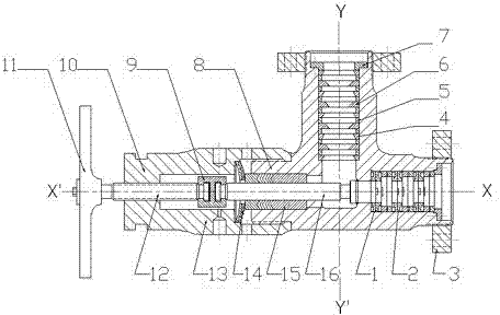
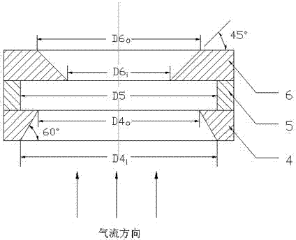
[0007] like figure 1 As shown, the present invention is a pressure reducing valve, including a valve body composed of a valve body 8 and a rotary valve cover 10, a compression packing sealing pair 15, a disc spring group 14 for sealing, and a rectangular hole guide plate 1 and the rectangular hole diverter plate 2 are superimposed to form a first-stage step-down, the diffuser ring 4, the distance ring 5 and the speed-increasing ring 6 are superimposed to form a second-stage step-down, and the gland 7 is pressed to fix the first-stage and second-stage The pressure-reducing group component, the valve stem is composed of an upper valve stem 12 and a lower valve stem 16, the middle of the two parts of the valve stem is connected by a split joint 9, and the upper valve stem 12 is rotated and lifted by the driving turntable 11.

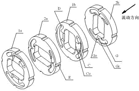
[0008] like figure 1 As shown, the rectangular hole diverter plate 1 and the rectangular hole diverter plate 2 are formed into a pair of rectangular hole ...


PUM


Abstract

The invention discloses a pressure reducing valve which aims at achieving a purpose of reducing pressure by enhancing a turbulence effect of media in the valve, intensifying flowing friction and collision of the media in a flowing process, and consuming the energy of the flowing media. The pressure reducing valve comprises a valve main body formed by a valve body (6) and a rotary valve cover (10), and is provided with a compaction packing seal pair (15) and a dish-shaped spring set (14) exerting a sealing effect, wherein a rectangular hole guide disk (1) and a rectangular hole shunt disk (2) are superposed to form primary pressure reduction; a pressure diffusion ring (4), a distance ring (5) and a speed increasing ring (6) are superposed to form secondary pressure reduction; a gland (7) compacts and fixes primary and secondary pressure reducing group elements; a valve rod consists of an upper valve rod (12) and a lower valve rod (16); the middles of the upper and lower valve rods are connected by a split joint (9); and the upper valve rod (12) is rotated and lifted by a driving turnplate (11).

Description

technical field [0001] The invention relates to a pressure reducing valve with a disc type pressure reducing element. Background technique [0002] In the prior art, most of the internal pressure-reducing components used in high-parameter pressure-reducing valves are sieve-type or labyrinth-type components, and the pressure-reducing effect is achieved through multi-stage shunting. Complicated and relatively expensive to process. Due to its narrow flow path, the instantaneous cavitation that may occur when the pipeline pressure fluctuates has a more obvious impact on the pressure reducing element, and the flow rate of the medium that can pass is also reduced accordingly. The traditional pressure relief valve has a narrow application range. In order to avoid the pressure relief element being blocked by small solid particles, it can only be applied to the pressure reduction of steam devices without solid particles in the medium. Contents of the invention [0003] The purpos...

Claims


Application Information

Patent Timeline
Patent Type & Authority Patents(China)
IPC IPC(8): F16K47/08
Inventor 余龙俞树荣
Owner 江苏洁特盛水暖有限公司
Why Eureka
Try Eureka