Backlight module

A technology of backlight module and light source module, applied in optics, light guide, light source and other directions, can solve the problem of affecting the light output area of ​​the backlight panel, etc.

Inactive Publication Date: 2013-08-14
XINCHENG TECH CHENGDU +1
View PDF7 Cites 3 Cited by
  • Summary
  • Abstract
  • Description
  • Claims
  • Application Information

AI Technical Summary

Problems solved by technology

However, due to the strong directivity of the light emitted by the light emitting diodes, when the distance between the light emitting diodes is large, it is easy to form a number of obvious "hot spots" on the light incident side of the light guide plate, and the hot spots cannot be used for Provide backlight, which affects the actual light emitting area of ​​the backlight panel

Method used


Image

  • Backlight module
  • Backlight module
  • Backlight module

Examples


Embodiment Construction

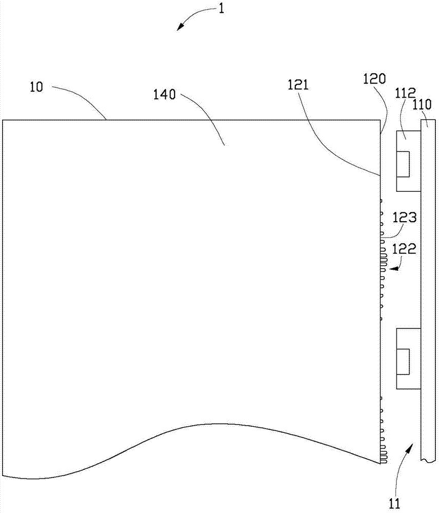
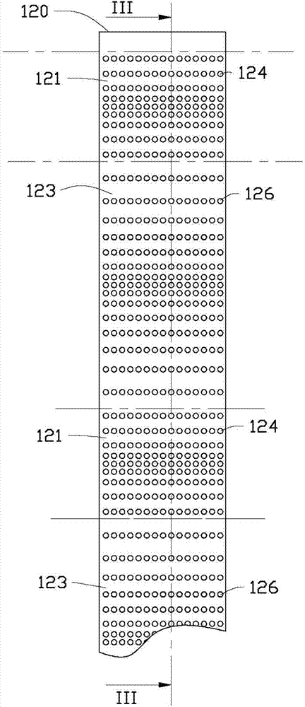
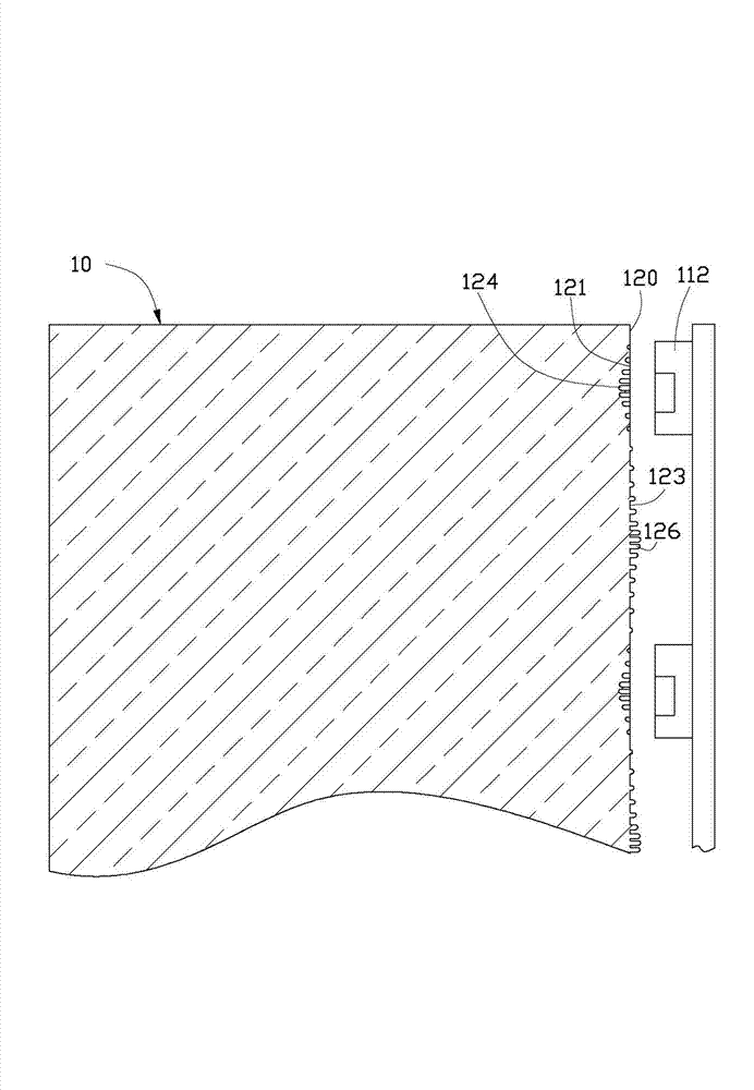
[0013] Such as figure 1 and figure 2 As shown, the backlight module 1 provided by the embodiment of the present invention includes a light guide plate 10 and a light source module 11 located on one side of the light guide plate 10 . The light guide plate 10 includes a light incident surface 120 and a light output surface 140 . In this embodiment, the light incident surface 120 is vertically connected to the light exit surface 140 . The light source module 11 is disposed facing the light incident surface 120 . The light emitted by the light source module 11 enters the light guide plate 10 through the light incident surface 120 and is fully mixed inside the light guide plate 10 before being emitted from the light output surface 140 .

[0014] In this embodiment, the light guide plate 10 is also a rectangular flat plate. The material of the light guide plate 10 is a transparent material, such as polymethyl methacrylate resin, methacrylic resin, polyacrylic resin, polycarbona...


PUM


Abstract

The invention provides a backlight module which comprises a light guide plate and a light source module located on one side of the light guide plate. The light guide plate comprises an incident surface and an emergent surface perpendicular to each other. The light source module right faces the incident surface and comprises a plurality of light-emitting parts which are disposed at intervals and which emit light. The incident surface is provided with dot microstructures which scatter the incoming light and which correspond to the light-emitting parts. The incident surface is also provided with dot microstructures which focus the incoming light and which correspond to the position between each two adjacent light-emitting parts.

Description

technical field [0001] The invention relates to a backlight module. Background technique [0002] Existing backlight modules generally include a light guide plate and a light source disposed on one side of the light guide plate. Most of the light sources use light-emitting diodes for the sake of energy saving and environmental protection. However, due to the strong directivity of the light emitted by the light emitting diodes, when the distance between the light emitting diodes is large, it is easy to form a number of obvious "hot spots" on the light incident side of the light guide plate, and the hot spots cannot be used for The provision of backlight affects the actual light emitting area of ​​the backlight panel. Contents of the invention [0003] In view of this, it is necessary to provide a backlight module capable of reducing the phenomenon of bright spots. [0004] A backlight module includes a light guide plate and a light source module located on one side of th...

Claims


Application Information

Patent Timeline
IPC IPC(8): F21S8/00F21V8/00F21Y101/02F21Y103/10F21Y115/10
Inventor 王智勇黄星童
Owner XINCHENG TECH CHENGDU
Why Eureka
Try Eureka