
Feeder maximum load estimation method for distribution transformers

A distribution transformer and maximum load technology, applied in the electric power field, can solve the problems of user power outage, waste of investment, no effective method for feeder, etc., and achieve the effect of reducing power outage events and high prediction accuracy.

Active Publication Date: 2015-10-28
SUZHOU CHINT ENTERPRISE DEV
View PDF7 Cites 0 Cited by
  • Summary
  • Abstract
  • Description
  • Claims
  • Application Information

AI Technical Summary

Problems solved by technology

If the transformer capacity configuration is too large, it will cause waste of investment; if the transformer capacity configuration is too small, and the switching operation cannot be arranged in advance, it will easily cause overload, or user power outages, which will easily lead to accidents
[0004] A single distribution transformer can supply power to multiple feeders. The maximum power load of each user on the same feeder usually does not reach the maximum value at the same time. Therefore, if the maximum power load of all users on the feeder is used to simply It is inaccurate to estimate the future maximum load of the feeder by superimposition, and it is easy to cause waste of investment in distribution transformers and feeder capacity
At present, there is no effective method for estimating the maximum load of the feeder in the future

Method used


Image

  • Feeder maximum load estimation method for distribution transformers
  • Feeder maximum load estimation method for distribution transformers
  • Feeder maximum load estimation method for distribution transformers

Examples


Embodiment Construction

[0028] The embodiments of the present invention will be described in further detail below in conjunction with the accompanying drawings, but the present embodiments are not intended to limit the present invention, and any similar structures and similar changes of the present invention should be included in the protection scope of the present invention.

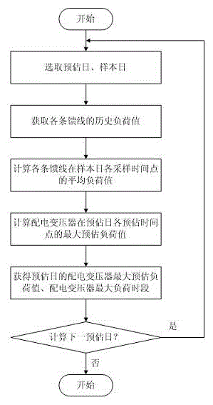
[0029] Such as figure 1 As shown, a method for estimating the maximum load of a distribution transformer feeder provided by an embodiment of the present invention is characterized in that the specific steps are as follows:

[0030] 1) Set a fixed sampling interval, denoted as ⊿T, where ⊿T usually takes 1 to 3 minutes;

[0031] 2) From the date of the current year, select a day as the estimated date;

[0032] 3) If there is no day in the previous year with the same month and date as the estimated date, select the day in the previous year that is the same month and the same day as the day before the estimated date as the sample...


PUM


Abstract

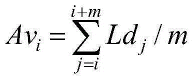
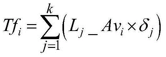
The invention discloses a method for predicating the maximum load of feeder lines of a distribution transformer, relates to the technical field of electric power, and aims to solve the technical problem that the future maximum load value of the distribution transformer cannot be accurately predicted. The method includes the steps as follows: firstly, historical load values of each feeder line in the year before a predicting day are acquired; then, an average load value of each feeder line at each sampling time of a sampling day is calculated on the basis of the historical load values; the maximum demand of daily declaration electricity is predicted on the basis of the calculated average load value and the historical maximum demand of daily declaration electricity, and the maximum prediction load value of the distribution transformer at each predicting time in the predicting day is calculated; the maximum value is chosen from the maximum prediction load values at each predicting time in the predicting day and taken as the maximum prediction load value of the distribution transformer in the predicting day; and the predicting time corresponding to the maximum prediction load value of the distribution transformer in the predicting day is taken as a time interval with the maximum load value of the distribution transformer in the predicting day. With the adoption of the method provided by the invention, investment waste of the volume of the feeder lines of the distribution transformer can be effectively avoided.

Description

technical field [0001] The invention relates to electric power technology, in particular to a method for estimating the maximum load of a feeder line of a distribution transformer. Background technique [0002] In the analysis of electricity consumption in the power system, in order to meet the needs of production and life, it is usually necessary to calculate the maximum capacity of customers’ electricity consumption in the future, so as to dispatch distribution transformers with appropriate capacity, or arrange reasonable switching methods. [0003] The power load of the feeder of the distribution transformer is changing, it is difficult to determine accurately, it can only be estimated based on certain experience, and the capacity of the distribution transformer of the substation is fixed after it is determined. If the transformer capacity configuration is too large, it will cause waste of investment; if the transformer capacity configuration is too small, and the switchi...

Claims


Application Information

Patent Timeline
Patent Type & Authority Patents(China)
IPC IPC(8): G01R31/00
Inventor 李昌宋丽华张溯宁
Owner SUZHOU CHINT ENTERPRISE DEV
Learn More