Rotary armature support mechanism for magnetic release

A technology of rotating armature and magnetic tripping, which is applied in the direction of protection switch operation/release mechanism, magnetic/electric field switch, protection switch parts, etc., which can solve the problems of assembly trouble and increased cost of magnetic tripper

Inactive Publication Date: 2016-12-28
SIEMENS AG
View PDF6 Cites 0 Cited by
  • Summary
  • Abstract
  • Description
  • Claims
  • Application Information

AI Technical Summary

Problems solved by technology

However, the solution with additional components increases the costs of such a magnetic release and is complicated to assemble

Method used


Image

  • Rotary armature support mechanism for magnetic release
  • Rotary armature support mechanism for magnetic release
  • Rotary armature support mechanism for magnetic release

Examples


Embodiment Construction

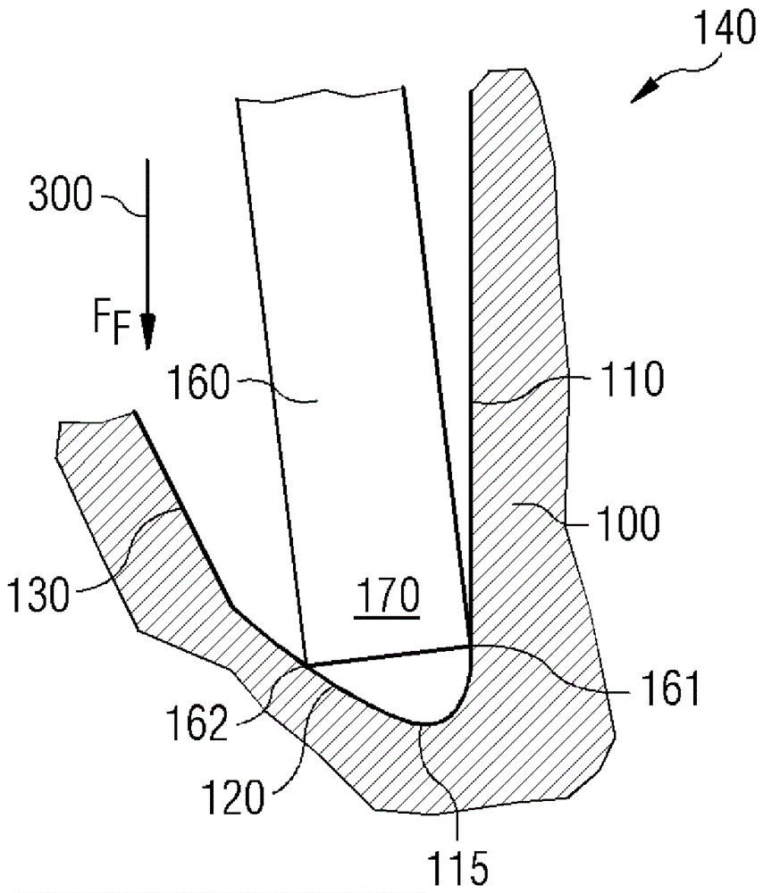
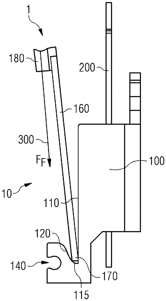
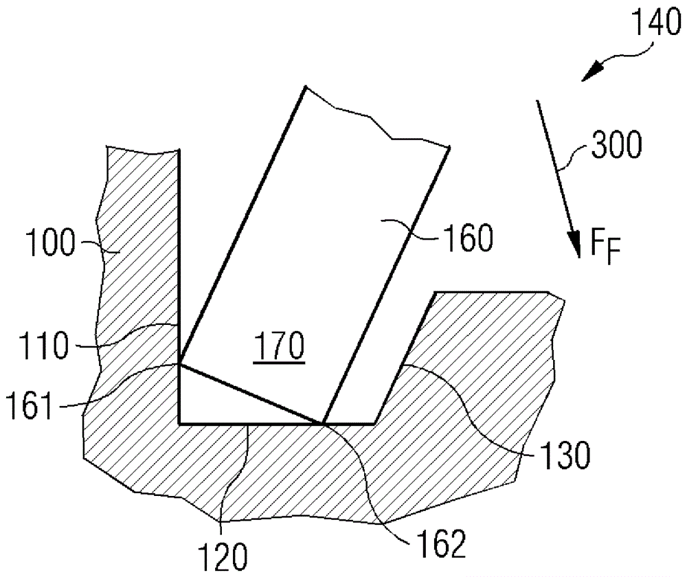
[0043] figure 1 with figure 2 A rotary armature bearing 140 is shown, as it is known from the prior art. The stop surface 110 , the support surface 120 and the contact surface 130 are formed as part of the magnetic yoke 100 . In particular, the stop surface 110 and the support surface 120 are arranged at an angle of 90° to one another. A first end 170 of the swivel armature 160 is inserted into the swivel armature bearing 140 . The spring force 300 acts on the second end 180 (not shown) of the rotating armature 160 . Swivel armature 160 is pressed into swivel armature bearing 140 by at least part of spring force 300 . The swivel armature 160 rests on one side against the contact surface 130 of the swivel armature bearing 140 , wherein the bearing edge 162 is arranged on the bearing surface 120 . However, the pivoting edge 161 is not arranged on the stop surface 110 . The spring force 300 also does not affect the movement of the rotating armature 160 so that the pivoting...


PUM


Abstract

Rotating armature support mechanism for magnetic releases. A rotary armature arrangement (10) for a magnetic release (1) of an electrical switching device, having a yoke (100), a rotary armature (160) and a spring force ( 300), wherein the swivel armature (160) is supported at a first end (170) in a swivel armature support (140), wherein the swivel armature support (140) has a bearing surface (120 ) and the stop surface (110), wherein said rotating armature spring is arranged on the rotating armature (160) in such a way that at least a first part of the spring force (300) acts against the magnetic force exerted when the electric rail (200) is energized On the swivel armature (160), wherein in particular the bearing surface (120) and the stop surface (110) are arranged at an angle α of less than 90° to one another.

Description

technical field [0001] The invention relates to a rotating armature support mechanism for a magnetic release of an electrical switching device, a magnetic release of an electrical switching device, and an electrical switching device. Background technique [0002] Magnetic releases for electrical switching devices are known in principle. In the conventional construction of a magnetic release, such a release consists in particular of three parts, namely a magnetic yoke, a swivel armature and a swivel armature spring. The swivel armature is preloaded by the swivel armature spring. A current flowing through a conductor or rail guided in the yoke induces a magnetic field in the yoke and in the rotating armature. The magnetic field exerts a force on the rotating armature in the air gap between the rotating armature and the yoke, which in particular counteracts at least part of the spring force. As soon as the current and the associated magnetic field induced by the current in t...

Claims


Application Information

Patent Timeline
Patent Type & Authority Patents(China)
IPC IPC(8): H01H71/24
CPCH01H71/2472H01H36/00
Inventor S.莱曼M.波莱斯
Owner SIEMENS AG
Why Eureka
Try Eureka