Hydraulic clamping device for molding machines

a technology of hydraulic clamping and molding machines, which is applied in the field of molding machines, can solve the problems of low productivity, large repercussions on the working cycle time of the entere, time consumption and complexity of handling the machine, and achieve the effects of fast opening and closing operations of molds, accurate and precise adjustment of clamping positions, and structurally simpl

Inactive Publication Date: 2005-09-20
ROMI ITAL
View PDF21 Cites 33 Cited by
  • Summary
  • Abstract
  • Description
  • Claims
  • Application Information

AI Technical Summary

Benefits of technology

[0024]There is consequently a need of a clamping device for molding machines which is structurally simple, allows a more accurate and precise adjustment of the clamping positions, and fast opening and closing operations of the molds for use in fast-cycle molding machines.

Problems solved by technology

In presses on molding machines of the aforesaid kind, in order to change the relative position of the two platens supporting the two mold members, and to adapt their disposition to molds of different thickness or size, it is necessary to change and adjust the axial extension of the tie bars by means of complicated operations which involve prolonged machine downtimes, resulting in a consequent low productivity.
The adjusting operations for adapting the press to molds of different thickness or size, as well as the time required for the opening and closing operations, have therefore considerable repercussions on the entere working cycle time.
In this type of machine also, the adjustment of the clamping position is obtained by means of wholly conventional systems, requiring again an adjustment of the axial extension of the tie bars as in the previous case; once again, all this entails time consumption and complexity in handling the machine, with a consequent negative influence on the working cycle.
The previously proposed solutions therefore involve complicated operations for carrying out all the necessary adjustments of the tie bars, as well as are time consuming for closing and clamping the molds, which are unsuitable for fast cycle molding machines.
Even though this solution permits an axial adjustment of the clamping device, in practice it appears to be again a somewhat complicated, due to that its requires costly machining operations to provide the screw threads along the tie bars, which must consequently undergo expensive surface treatments in order to withstand the high contact forces, which would otherwise cause deformation and considerable wear.
Moreover, the time required for adjusting the stop members and for clamping the locking jaws, is still comparatively long with respect to cycle times in the range of seconds, for fast-cycle machines.
This solution also substantially presents the same drawbacks as the previous devices.

Method used


Image

  • Hydraulic clamping device for molding machines
  • Hydraulic clamping device for molding machines
  • Hydraulic clamping device for molding machines

Examples


Embodiment Construction

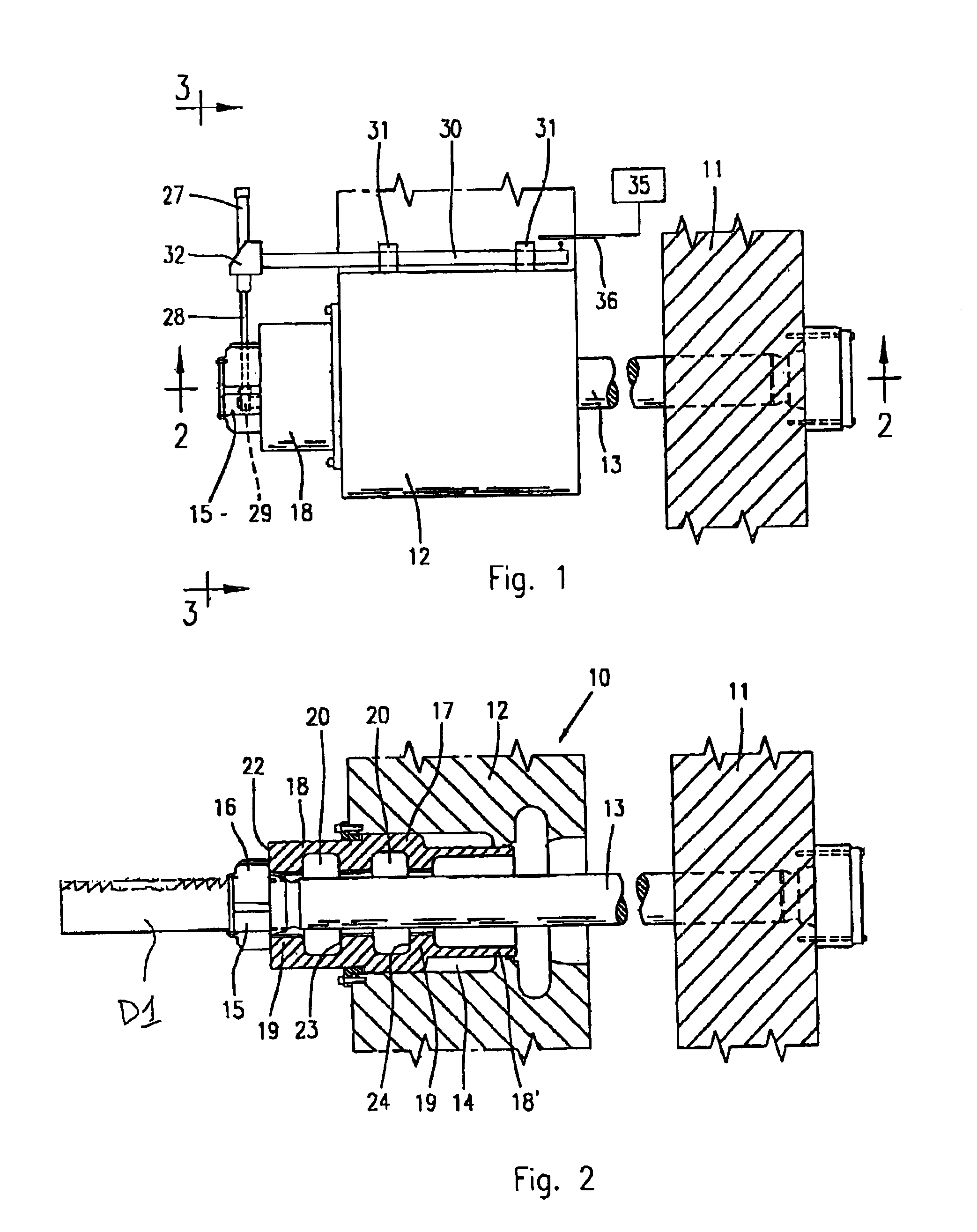
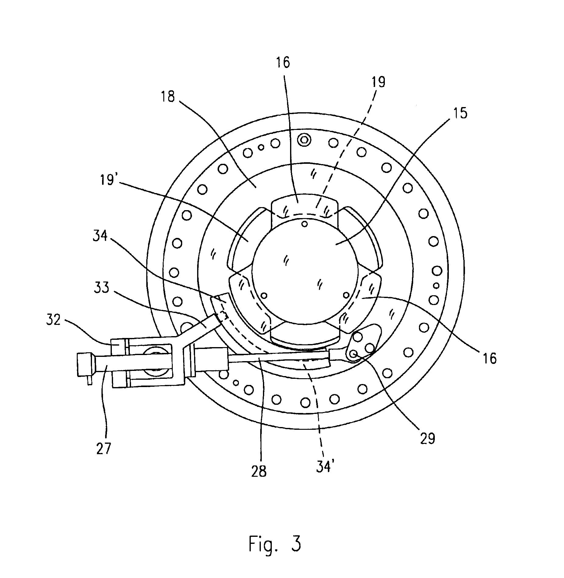
[0044]With reference to the FIGS. 1 to 3, a description will be now given of a first embodiment of a clamping device according to the invention for an injection molding machine.

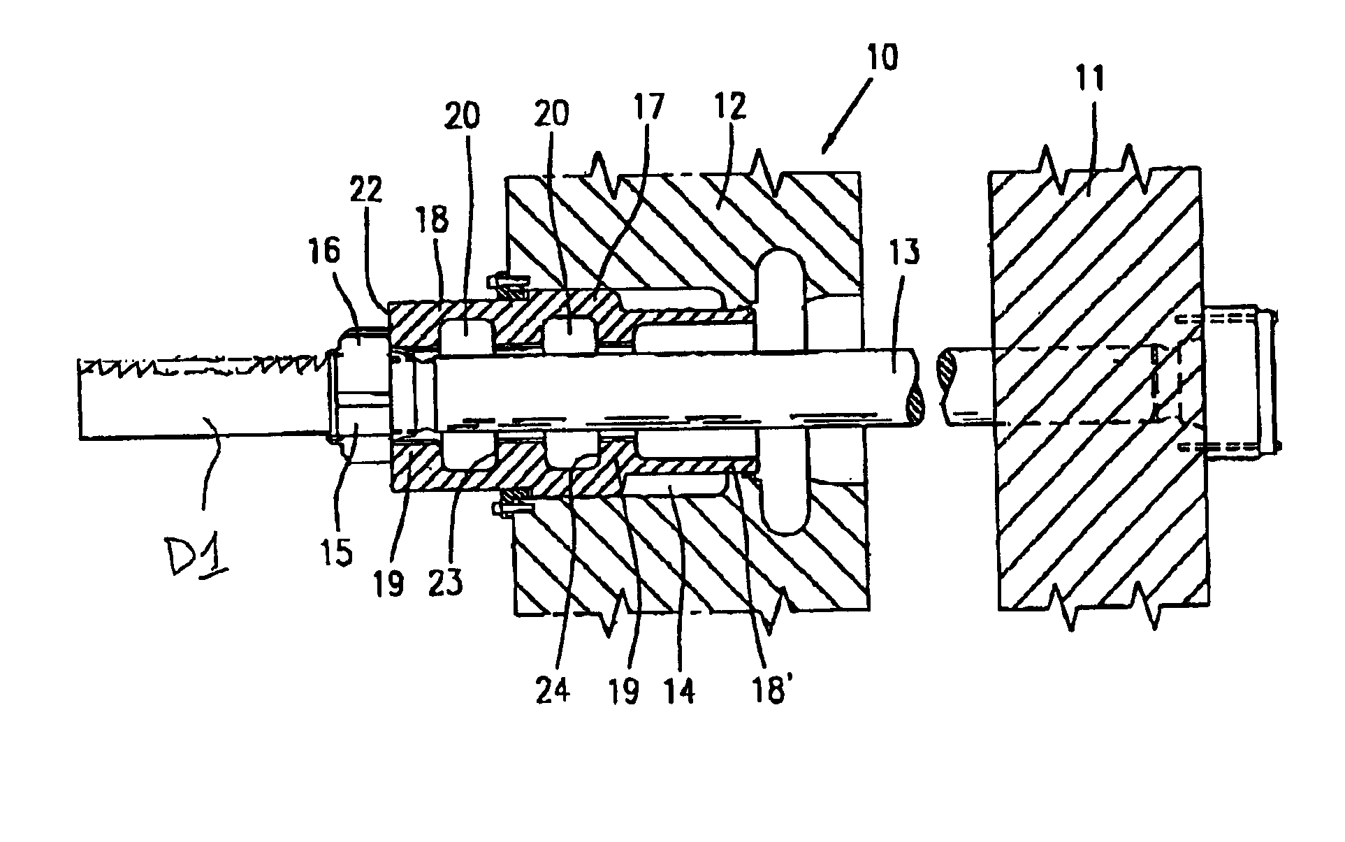
[0045]The clamping device, generically indicated by the reference number 10, extends between a first and a second structural frame member, for example between a first mold-support platen 11 and a second mold-support platen 12 one of which is movable in relation to the other one to reciprocate between a first mold closing position and, respectively, a second opening position for a mold having a given thickness or size.

[0046]In the example of FIGS. 1-3, the clamping device comprises a tie bar 13 for transmitting the clamping force, fastened to the platen 11; the tie-bar 13 extends towards and through clamping means on the platen 12, comprising a clamping sleeve and piston unit 17, 18 of a hydraulic control cylinder 14, as shown.

[0047]In particular, the tie bar 13 at its free end is provided with a toothed head ...


PUM

PropertyMeasurementUnit
mold-thicknessaaaaaaaaaa
mold thicknessaaaaaaaaaa
thicknessaaaaaaaaaa

Abstract

The clamping comprises a tie-bar which extends between a fixed and a movable platen of a molding machine, with respect to the first, and hydraulically operated locking means for engaging the tie bar and generating the clamping force. The locking means comprises a hydraulic cylinder having a hollow sleeve and piston provided with internal toothings, in axially spaced apart positions. The sleeve and piston unit is made to rotate and slide axially, to selectively engage and disengage with the toothed head at the end of the tie bar to allow step and fine adjustments of the position of the movable platen, in relation to the thickness of the mold.

Description

BACKGROUND OF THE INVENTION[0001]This invention refers to the general field of the molding machines, such as injection molding, die casting and press molding machines; in particular the invention is directed to a clamping device for clamping the mold-support platens of a molding machine, suitable for allowing the tightening and the adjustment of the platens in a plurality of clamping positions for molds of different thickness and size.[0002]The invention is also directed to a molding machine of the type previously referred to, provided with a similar adjustable clamping device.[0003]In several molding fields, for example in the injection molding field for plastic materials, there exist several types of molding machines or presses which make use of different mechanisms or clamping systems for locking the mold support platens, which allow a certain degree of adjustment for molds of different thickness and size.[0004]Usually such molding machines comprise a stationary or fixed mold-sup...

Claims


Application Information

Patent Timeline
Patent Type & Authority Patents(United States)
IPC IPC(8): B29C45/67B29C45/17
CPCB29C45/1751B29C45/6728B29C2045/6735
Inventor ROETZEL, HARTMUT
Owner ROMI ITAL
Why Eureka
Try Eureka