Dispensing valve

A technology of dispensing valves and colloids, which is applied in the direction of coatings and devices for coating liquid on the surface, which can solve the problems of inability to fine-tune, low work efficiency, and short equipment life, and achieve high dispensing accuracy and high dispensing accuracy , good air tightness effect

Inactive Publication Date: 2017-06-06
SUZHOU TERUITE ROBOT CO LTD
View PDF3 Cites 5 Cited by
  • Summary
  • Abstract
  • Description
  • Claims
  • Application Information

AI Technical Summary

Problems solved by technology

[0002] With the improvement of automation in the field of dispensing, the demand for dispensing accuracy is also gradually increasing, and the contradiction between dispensing efficiency and dispensing accuracy is also prominent. In the existing dispensing valve mechanism, the piston generally relies on The push and compression of the elastic element (such as a spring) realizes sliding up and down. While the elastic element slides, the elastic diaphragm deforms to transport the external glue into the glue storage chamber, and at the same time further drives the dispensing plug to slide up and down quickly to reach the start point. / Close the purpose of dispensing. In this dispensing valve, the amount of dispensing is determined by the deformation of the elastic diaphragm. The upper and lower ends of the elastic diaphragm need a temporary storage structure for external glue, which is bound to affect the sealing performance of the dispensing valve. The requirements are more stringent, the equipment is more vulnerable to damage, and the life of the equipment is shorter
[0003] Secondly, during the working process of the dispensing valve, it is impossible to fine-tune directly from the outside of the motor valve body. When changing the dispensing amount, it is usually to disassemble the dispensing valve as a whole, adjust its internal structure, and then reassemble it. Moreover, the problem of poor sealing often occurs during the assembly process, and the work efficiency is extremely low.

Method used


Image

  • Dispensing valve
  • Dispensing valve
  • Dispensing valve

Examples


Embodiment Construction

[0020] The following will clearly and completely describe the technical solutions in the embodiments of the present invention with reference to the accompanying drawings in the embodiments of the present invention. Obviously, the described embodiments are only some, not all, embodiments of the present invention. Based on the embodiments of the present invention, all other embodiments obtained by persons of ordinary skill in the art without creative efforts fall within the protection scope of the present invention.

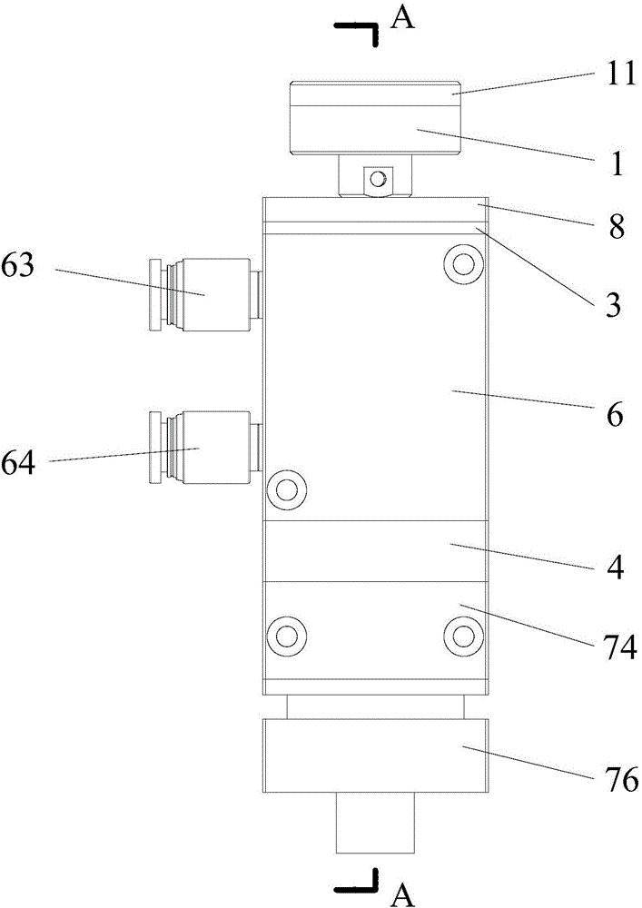
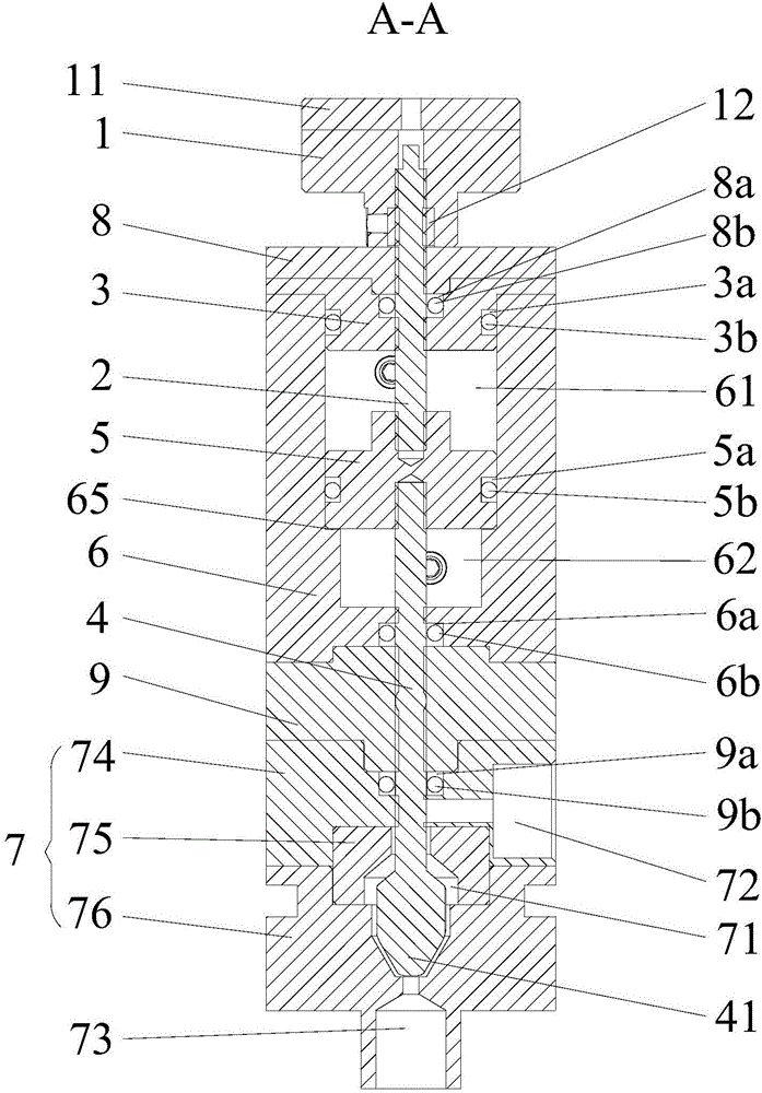
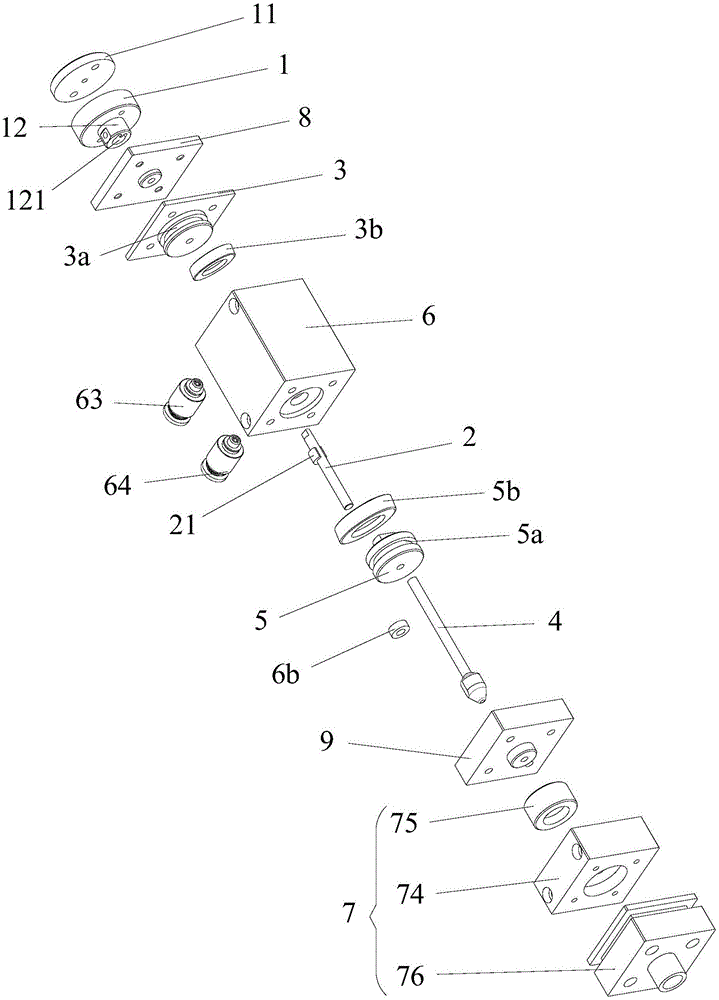
[0021] The present invention provides a glue dispensing valve, which includes stroke fine-tuning knob 1, adjusting rod 2, adjusting rod fixing seat 3, plunger rod 4, piston 5, hollow cylinder body 6 and glue storage body 7, adjusting rod fixing seat 3 The outer side of the lower end is pressed and fixed on the inner side wall of the upper end of the cylinder body 6. The upper end of the adjustment rod holder 3 is fixedly installed on the end of the cylinder body 6 c...


PUM


Abstract

The invention discloses a dispensing valve. The dispensing valve comprises a stroke fine tuning rotary knob, an adjusting rod, an adjusting rod fixing base, a plunger rod, a piston, a hollow cylinder body and an adhesive storing body. Accurate dispensing is conducted by controlling the air pressure; in addition, the dispensing quantity can be controlled through the coordinating function between the external stroke fine tuning rotary knob and the adjusting rod; the whole dispensing valve does not need to be disassembled; using is simple and easy; and the service life is long.

Description

technical field [0001] The invention relates to the technical field of dispensing equipment, in particular to a dispensing valve. Background technique [0002] With the improvement of automation in the field of dispensing, the demand for dispensing accuracy is also gradually increasing, and the contradiction between dispensing efficiency and dispensing accuracy is also prominent. In the existing dispensing valve mechanism, the piston generally relies on The push and compression of the elastic element (such as a spring) realizes sliding up and down. While the elastic element slides, the elastic diaphragm deforms to transport the external glue into the glue storage chamber, and at the same time further drives the dispensing plug to slide up and down quickly to reach the start point. / Close the purpose of dispensing. In this dispensing valve, the amount of dispensing is determined by the deformation of the elastic diaphragm. The upper and lower ends of the elastic diaphragm nee...

Claims


Application Information

Patent Timeline
Patent Type & Authority Applications(China)
IPC IPC(8): B05C5/02B05C11/10
CPCB05C5/0225B05C11/1026
Inventor 陈晓峰
Owner SUZHOU TERUITE ROBOT CO LTD
Why Eureka
Try Eureka