Dispensing jig

A technology of dispensing and jig, applied in the direction of coating, the device for coating liquid on the surface, etc., can solve the problems such as the position of the dispensing device is not adjustable, it is difficult to meet the production of large-scale button assembly, and the adaptability is not strong. Improves dispensing efficiency, versatility and dispensing accuracy

Inactive Publication Date: 2016-11-16
KESEN SCI & TECH DONGTAI CO LTD
View PDF8 Cites 4 Cited by
  • Summary
  • Abstract
  • Description
  • Claims
  • Application Information

AI Technical Summary

Problems solved by technology

Existing dispensing devices generally can only dispense one part at a time, which is difficult to meet the mass production of button assembly. Some dispensing devices are equipped with multiple dispensing syringes, which can

Method used


Image

  • Dispensing jig
  • Dispensing jig
  • Dispensing jig

Examples


Embodiment 1

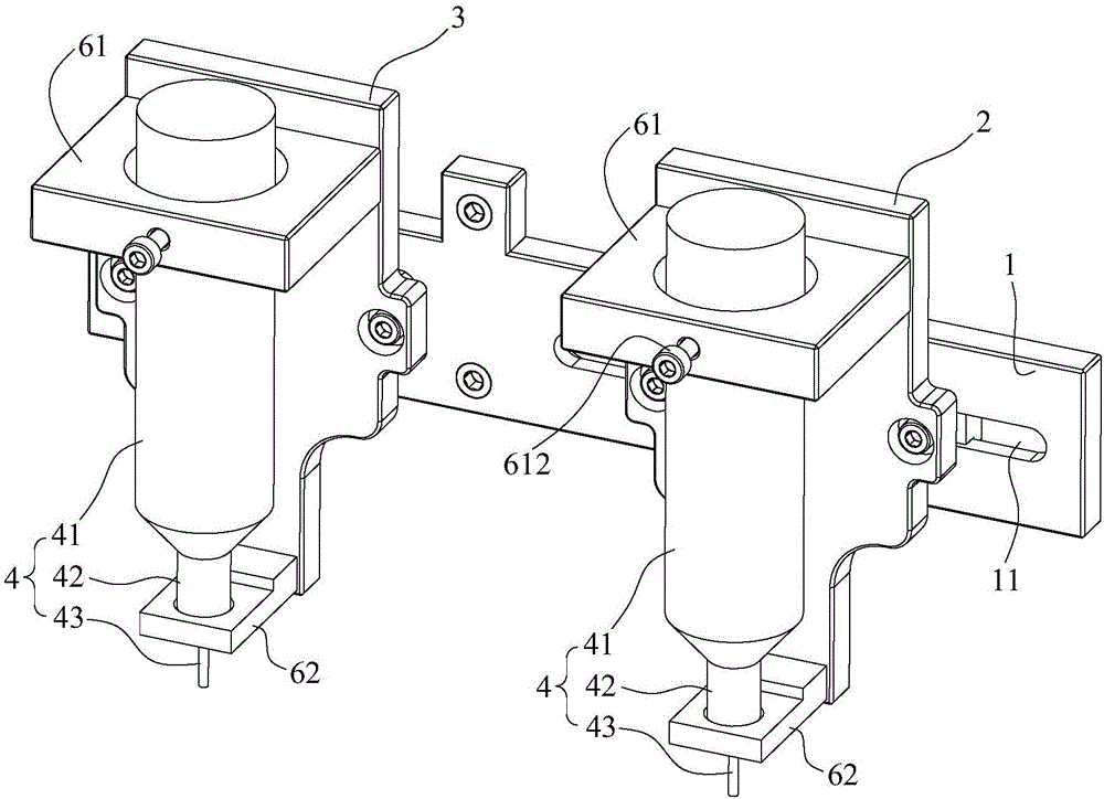
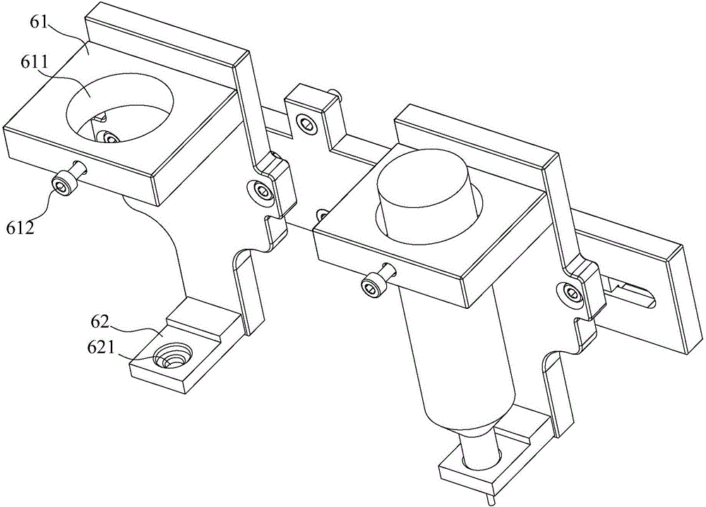
[0024] refer to Figure 1-Figure 4 , the present embodiment provides a dispensing fixture, including a fixture support 1, a first dispensing support 2 and a second dispensing support 3, the first dispensing support 2 and the second dispensing support 3 are used for fixing The dispensing syringe 4 and the jig bracket 1 are fixed on the dispensing machine. The first dispensing bracket 2 can slide along the surface of the jig bracket 1 in the transverse direction, and the second dispensing bracket 3 can slide along the surface of the jig bracket 1 in the longitudinal direction. Direction slide. The two dispensing syringes 4 can dispens glue to two parts at the same time, which improves the dispensing efficiency, and the first glue dispensing bracket 2 and the second glue dispensing bracket 3 can slide horizontally and vertically along the surface of the jig bracket 1 respectively, The position between the first glue dispensing bracket 2 and the second glue dispensing bracket 3 c...

Embodiment 2

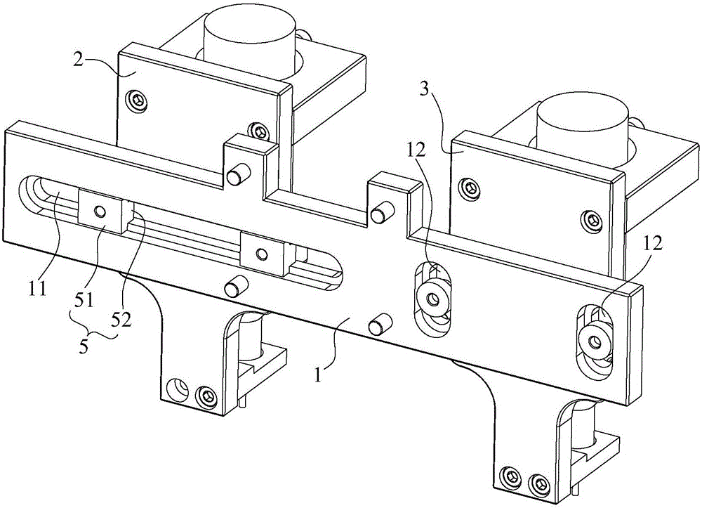
[0030] Different from Embodiment 1, a plurality of horizontal strip-shaped holes 11 parallel to each other are arranged horizontally on the fixture bracket 1, and the horizontal strip-shaped holes 11 are all stepped holes, and the T-shaped block 5 passes through the horizontal strip-shaped holes 11 and is fixed on the The first dispensing support 2, the rib 51 of the T-shaped block 5 abuts against the stepped portion of the transverse strip hole 11, the T-shaped block 5 and the first dispensing support 2 are fixed by bolts, and the T-shaped block 5 and the first dispensing support 2 are fixed by bolts. The tightness between the first glue dispensing bracket 2, loosen the bolt and slide the first glue dispensing bracket 2, and when it slides to the predetermined position, tighten the bolt to firmly clamp the T-shaped block 5 and the first glue dispensing bracket 2 to the stepped part To ensure that the position of the first glue dispensing bracket 2 does not change any longer, e...

Embodiment 3

[0032] The difference from Embodiment 1 is that a longitudinal strip hole 12 is longitudinally arranged on the fixture bracket 1, and the longitudinal strip hole 12 is a stepped hole, and a plurality of T-shaped blocks 5 pass through the longitudinal strip hole 12 and are fixed on the first Two dispensing brackets 3, to ensure that the second dispensing bracket 3 slides along the longitudinal strip hole 12, the rib 51 of the T-shaped block 5 abuts against the stepped portion of the longitudinal strip hole 12, the rib 51 and the second dispensing bracket 3. Clamp the stepped portion of the longitudinal strip hole 12 in the middle, fix the T-shaped block 5 and the second dispensing bracket 3 with bolts, adjust the tightness between the T-shaped block 5 and the second dispensing bracket 3 through the bolts, and turn Loosen the bolt and slide the second dispensing bracket 3, and tighten the bolt when sliding to the predetermined position to firmly clamp the T-shaped block 5 and the...


PUM


Abstract

The invention discloses a dispensing jig. The dispensing jig comprises a jig support, a first dispensing support and a second dispensing support. The first dispensing support and the second dispensing support are used for fixing dispensing injectors. The jig support is fixed to a dispensing machine. The first dispensing support can slide along the surface of the jig support in the transverse direction. The second dispensing support can slide along the surface of the jig support in the longitudinal direction. The two dispensing injectors can conduct dispensing on two components at the same time, and the dispensing efficiency is improved. Due to the fact that the first dispensing support can slide along the surface of the jig support in the transverse direction, and the second dispensing support can slide along the surface of the jig support in the longitudinal direction, the position between the first dispensing support and the second dispensing support can be accurately adjusted, the two dispensing positions are accurately adjusted, and universality and the dispensing precision are improved.

Description

technical field [0001] The invention relates to the technical field of glue dispensing tools, in particular to a glue dispensing jig. Background technique [0002] At present, most of the mobile phone keys are made of aluminum. In order to ensure the performance and user experience, the back of the mobile phone keys needs to be glued with rubber. Existing dispensing devices generally can only dispense one part at a time, which is difficult to meet the mass production of button assembly. Some dispensing devices are equipped with multiple dispensing syringes, which can dispensing multiple parts at the same time, but each dispensing device The position is not adjustable, and it can only be dispensed for parts whose dispensing position is completely fixed, and the adaptability is not strong. Contents of the invention [0003] The object of the present invention is to propose a dispensing jig, which can dispens glue to two parts at the same time, which improves the dispensing ...

Claims


Application Information

Patent Timeline
IPC IPC(8): B05C5/02
CPCB05C5/027B05C5/0295
Inventor 吴惠明王海明李忠洋严应保
Owner KESEN SCI & TECH DONGTAI CO LTD
Why Eureka
Try Eureka