Adhesive dispensing mechanism and display screen production line

A dispensing mechanism and dispensing technology, applied in the direction of coating, liquid coating device on the surface, etc., can solve the problem of low dispensing efficiency, low precision of dispensing detection, and the inability to observe whether the dispensing valve is smooth or not in real time , Whether the amount of glue is up to the standard, etc., to achieve the effect of high dispensing efficiency, high dispensing precision and high work efficiency

Pending Publication Date: 2020-06-19
KUNSHAN SAMON AUTOMATION TECH
View PDF0 Cites 5 Cited by
  • Summary
  • Abstract
  • Description
  • Claims
  • Application Information

AI Technical Summary

Problems solved by technology

The dispensing mechanism of the prior art, on the one hand, has the problems of low dispensing accuracy and low dispensing efficiency; on the other hand, for large-sized display screens, the staff cannot observe in real time whether the dispensing valve is dispensing smoothly and whether the dispensing is smooth or not. Whether the amount of glue reaches the standard and other working conditions

Method used


Image

  • Adhesive dispensing mechanism and display screen production line
  • Adhesive dispensing mechanism and display screen production line
  • Adhesive dispensing mechanism and display screen production line

Examples


Embodiment 1

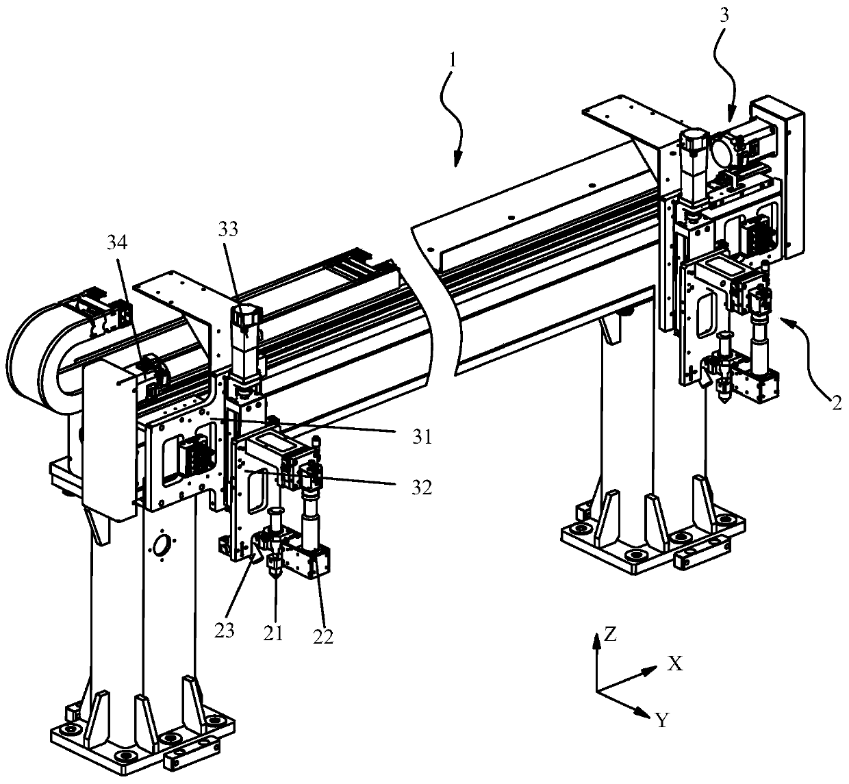
[0050] Such as figure 1As shown, the X direction in the figure is the extension direction of the gantry, the Y direction is the moving direction of the workpiece, and the Z direction is the vertical direction. The X, Y and Z directions are perpendicular to each other, and the X, Y and Z directions are only Represents the spatial direction and has no practical significance. This embodiment is especially applicable to the step of coating the conductive silver paste at the terminals of the CF layer and the TFT layer to short-circuit them. The dispensing mechanism includes a gantry 1, two sets of dispensing modules 2 and a moving module 3. The gantry 1 forms a space in the X-Z plane for the workpiece to pass through along the Y direction; two sets of dispensing modules 2 are respectively arranged in the X direction of the gantry 1. The two ends are used for dispensing the workpiece; the moving module 3 is used to drive the dispensing module 2 to move along the X and Z directions ...

Embodiment 2

[0061] This embodiment is especially suitable for coating the insulating resin glue at the terminal connecting the display panel and the COF. This embodiment differs from Embodiment 1 in that:

[0062] Such as Figure 4 As shown, the dispensing mechanism also includes a curing component 4 for curing the glue. The curing component 4 is connected to the mobile module 3. The dispensing valve 21, the CCD detection component 22 and the curing component 4 are collinear and arranged in sequence along the X direction. The curing component 4 can quickly cure the insulating resin glue that has just been placed to avoid the flow of the glue; the dispensing valve 21, the CCD detection component 22 and the curing component 4 are arranged on the same line along the X direction, so as to ensure that the moving module 2 is aligned along the X direction. In the process of direction movement, it can not only complete dispensing, inspection of dispensing quality and colloid curing at the same t...


PUM


Abstract

The invention relates to the technical field of display screen production, and discloses an adhesive dispensing mechanism and a display screen production line. The adhesive dispensing mechanism comprises a portal frame, two sets of adhesive dispensing modules and a moving module, the portal frame forms a space allowing a workpiece to penetrate in the Y direction in the X-Z plane, the two sets of adhesive dispensing modules are arranged at two ends of the portal frame in the X direction respectively and used for adhesive dispensing the workpiece, and the moving module is used for driving the adhesive dispensing modules to move in the X direction and the Z direction relative to the portal frame; and each adhesive dispensing module comprises a adhesive dispensing valve, a CCD detection component and a camera, the position of the adhesive dispensing valve is adjustable relative to the portal frame in the Y direction, the CCD detection component is used for detecting the dispensing quality,and the camera is used for shooting the working state of the adhesive dispensing valve. The adhesive dispensing mechanism disclosed by the invention is high in working efficiency, and the working state of the dispensing valves and the adhesive dispensing quality can be observed in real time. According to the display screen production line disclosed by the invention, through the adhesive dispensing mechanism, the display screen production efficiency is high, the dispensing precision is high, and problems in production can be conveniently observed in real time.

Description

technical field [0001] The invention relates to the technical field of display screen production, in particular to a glue dispensing mechanism and a display screen production line. Background technique [0002] The display screen usually includes a display panel and a PCB board (Printed Circuit Board, printed circuit board). The display panel and the PCB board are connected by COF (Chip on film, chip on film). ) layer and TFT (Thin Film Transistor, thin film transistor) layer, it is necessary to apply insulating resin glue at the terminal connected to the display panel and COF, and to apply conductive silver glue at the terminal position to make the CF layer and TFT The layer is short connected. [0003] When dispensing glue, the display screen is usually fixed, and the dispensing valve moves in a preset direction to apply the corresponding glue on the corresponding position of the display screen. The dispensing mechanism of the prior art, on the one hand, has the problems...

Claims


Application Information

Patent Timeline
Patent Type & Authority Applications(China)
IPC IPC(8): B05C9/14B05C5/02B05C11/10
CPCB05C5/0216B05C9/14B05C11/1005
Inventor 张青山李柏龄陈涛
Owner KUNSHAN SAMON AUTOMATION TECH
Why Eureka
Try Eureka