Method for regulating spacing during laser machining process

A technology of laser processing and laser processing head, which is applied in the direction of laser welding equipment, metal processing equipment, manufacturing tools, etc., can solve the problem of poor measurement resolution of measurement time intervals, and achieve the effect of improving dynamics

Active Publication Date: 2018-08-24
PRECITEC GMBH
View PDF6 Cites 1 Cited by
  • Summary
  • Abstract
  • Description
  • Claims
  • Application Information

AI Technical Summary

Problems solved by technology

The shortening of the measuring time intervals required for high measuring rates and high dynamics of the distance adjustment then leads to a reduction in the measuring resolution and as a result, especially at greater distances between nozzle and workpiece Accurate distance measurement in case of time intervals

Method used


Image

  • Method for regulating spacing during laser machining process
  • Method for regulating spacing during laser machining process

Examples


Embodiment Construction

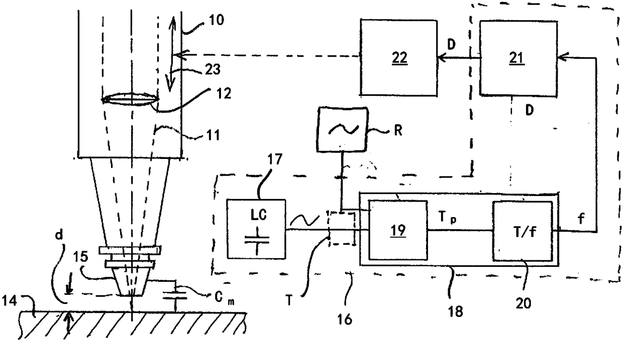
[0017] figure 1 A laser processing head 10 of a laser processing device is shown schematically, through which a working laser beam 11 is focused onto a workpiece 14 by means of a focusing lens 12 . In order to measure the distance d between the nozzle tip 15 of the laser processing head 10 and the workpiece 14, the capacitance Cm between the nozzle tip 15 and the workpiece 14 is connected to the resonant circuit, in particular the LC resonant circuit 17 of the distance sensor 16 . The LC resonant circuit used in the exemplary embodiment with a fundamental frequency in the range of approximately 10 MHz oscillates in a suitable manner. The basic frequency of the LC resonant circuit can also be selected from the range of 9 MHz to 11 MHz or preferably from the range of 9.5 MHz to 10.5 MHz. The output signal of the LC-oscillating circuit 17 , which is related to the capacitance Cm between the workpiece 14 and the nozzle tip 15 , is supplied to a circuit 18 which determines the pe...


PUM


Abstract

The invention relates to a method for regulating a spacing during a laser machining process using an electric resonant circuit (17), the oscillation frequency of which depends on the spacing between alaser machining head (10) and a workpiece (14), and an adjusting device (23) for adjusting the spacing (d) between the laser machining head (10) and the workpiece (14). The aim of the invention is toallow a precise measurement of the spacing between the laser machining head (10) and the workpiece (14) with the precision and measurement rate required for the machining process. According to the invention, this is achieved in that the period duration of the resonant circuit signal is measured, and the spacing (d) between the laser machining head (10) and the workpiece (14) is ascertained on thebasis of the measured period duration of the resonant circuit signal and fed to the adjusting device (23).

Description

technical field [0001] The invention relates to a method for adjusting the distance during laser processing using an electric resonant circuit whose oscillation frequency is dependent on the distance between the laser processing head and the workpiece. For dynamic distance control during laser processing, especially during laser cutting or laser welding, precise measurement of the actual distance between laser processing head and workpiece is required with the highest possible measurement rate. Background technique [0002] A known type of measurement of the distance between the laser processing head and the workpiece, or more precisely between the nozzle tip of the laser processing head and the workpiece, is the analytical processing of the capacitance between the nozzle tip and the workpiece, by which nozzle tip The working laser beam is emitted and possible process gas flows at high pressure through the nozzle tip into the interaction region between the working laser beam...

Claims


Application Information

Patent Timeline
Patent Type & Authority Applications(China)
IPC IPC(8): G01B7/02
CPCB23K26/048G01B7/023
Inventor G·施珀尔M·蒂埃尔
Owner PRECITEC GMBH
Why Eureka
Try Eureka