
A waste heat recovery system of a vacuum conditioner

A technology of waste heat recovery system and vacuum resurfacing, applied in heat exchanger types, indirect heat exchangers, lighting and heating equipment, etc., can solve the problems of popularization and application restrictions, hot water pollution, environmental impact, etc., and achieve large heat dissipation area, Sufficient heat recovery capability and long service life

Active Publication Date: 2016-03-02
CHINA TOBACCO HENAN IND
View PDF8 Cites 0 Cited by
  • Summary
  • Abstract
  • Description
  • Claims
  • Application Information

AI Technical Summary

Problems solved by technology

The suction vacuum is realized by steam ejector pump, which consumes 330kg of steam per batch (pot), and the residual steam formed by these steam is generally introduced into the outdoor as waste steam and directly discharged to the air, which not only causes waste of heat energy but also harms the environment. certain influence
At present, there are generally two ways to recover heat energy from residual steam at home and abroad. One is direct absorption, and the other is heat exchange absorption. The hot water is polluted and cannot be used directly, requiring secondary heat exchange, and the heat dissipation is serious. Therefore, although it is used in cigarette factories, its promotion and application are limited; the latter is absorbed by a heat exchanger, and the recovered hot water can be directly used and recovered High efficiency, but there are special design requirements for heat exchanger tube resistance

Method used


Image

  • A waste heat recovery system of a vacuum conditioner
  • A waste heat recovery system of a vacuum conditioner
  • A waste heat recovery system of a vacuum conditioner

Examples


Embodiment Construction

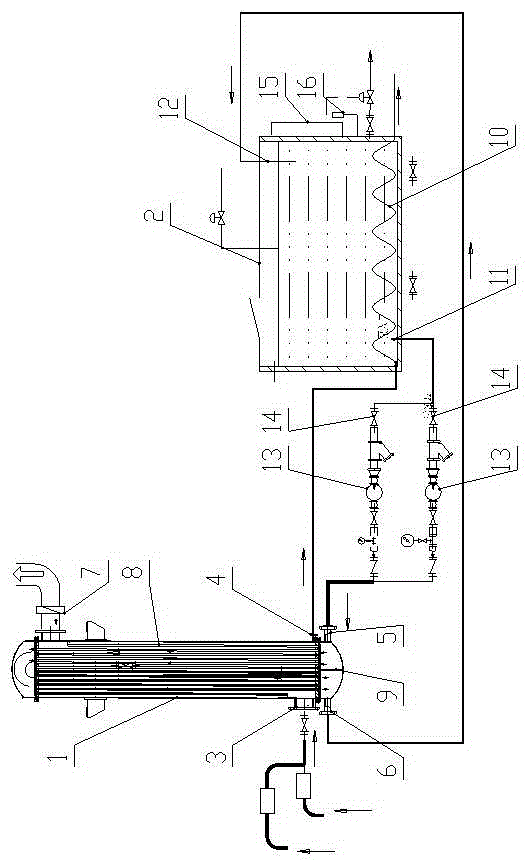
[0026] Such as figure 1 As shown, the present invention condenses the residual steam originally discharged to the air through the heat exchanger, and the heat energy is absorbed by the cooling water, and the cooling water is heated repeatedly. After increasing the temperature of the heated cooling water, the cooling water can be reused.

[0027] Such as figure 1 As shown, the present invention includes a condenser 1 and a circulating water tank 2 .

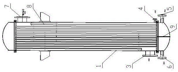
[0028] Such as figure 2 As shown, the lower part of the condenser 1 is provided with four ports, which are steam inlet 3 , condensed water outlet 4 , circulating water inlet 5 , and circulating water outlet 6 . The steam inlet 3 is connected with the damp conditioner through a steam pipeline. The condensed water outlet 4 and the circulating water outlet 6 are connected to the circulating water tank 2 through pipelines. The top of the condenser 1 is provided with a discharge port 7 . A deflector 8 is provided near the inner w...


PUM


Abstract

A waste heat recovery system for a vacuum moisture conditioner, including a condenser and a circulating water tank, the lower part of the condenser is provided with a steam inlet, a condensed water outlet, a circulating water inlet, and a circulating water outlet, and the condensed water outlet and the circulating water outlet are connected through a pipeline. The circulating water tank is connected, the circulating water inlet is connected with the circulating water tank through a circulating pump, the circulating water tank is provided with a cooling pipe, and the condensed water outlet is connected with the cooling tube through a pipeline. The invention starts from reducing the tube resistance of the heat exchanger and improving the heat exchange efficiency, and conforms to the characteristics of instantaneous, intermittent and large flow of the residual steam discharged by the steam ejection of the jet vacuum humidifier, and uses the radiator as a steam residual steam condenser With structural design, it can be used as a supporting product for this type of vacuum conditioning machine.

Description

technical field [0001] The invention relates to a vacuum dampening machine, in particular to a waste heat recovery device for the vacuum dampening machine. Background technique [0002] Jet-type vacuum dampening machine is currently widely used in the tobacco silk production line. The vacuum dampening machine is the key process equipment of the silk production line. Its function is to suck the tobacco sheets stored in the cylinder into a negative pressure of 9.80kpa (absolute pressure) Vacuum is used to complete the process of expanding and loosening laminar tobacco, removing green and miscellaneous gases, killing insects, and increasing temperature and humidity. The suction vacuum is realized by steam ejector pump, which consumes 330kg of steam per batch (pot), and the residual steam formed by these steam is generally introduced into the outdoor as waste steam and directly discharged to the air, which not only causes waste of heat energy but also harms the environment. cer...

Claims


Application Information

Patent Timeline
Patent Type & Authority Patents(China)
IPC IPC(8): F28D7/00F28B1/02A24B3/04
CPCY02P70/50
Inventor 牛社民张蒙生罗健靳光磊万永华尚良君唐培丽黄会民赵新民刘建军赵东峰徐正义
Owner CHINA TOBACCO HENAN IND
Learn More