
Surface cleaning device

A surface cleaning device and cleaning technology, applied to cleaning equipment, window cleaning, household appliances, etc., can solve the problems of high cost, weakened suction force, complex structure, etc., and achieve strong suction force, smooth air path, and structure simple effect

Active Publication Date: 2013-08-21
ZHONGSHAN JINSHUN HOUSEHOLD WARES +1
View PDF9 Cites 33 Cited by
  • Summary
  • Abstract
  • Description
  • Claims
  • Application Information

AI Technical Summary

Problems solved by technology

[0003] In order to simultaneously suck away the liquid on the glass surface in time when cleaning the surface of a hard object such as a glass surface, a patent with a publication number of CN101909499B discloses a portable hard surface suction device, but it has the following defects: 1. Because the liquid suction path is separated from the external air suction path, the suction force is weakened, and when the liquid and external air are sucked in and separated from water and gas by the water baffle, the liquid can only rely on itself Weight enters the inside of the tank and cannot quickly pump liquid into the inside of the tank
2. At the same time, it also has the defects of complex structure and high cost, and cannot be popularized and applied in large quantities

Method used


Image

  • Surface cleaning device
  • Surface cleaning device
  • Surface cleaning device

Examples


Embodiment Construction

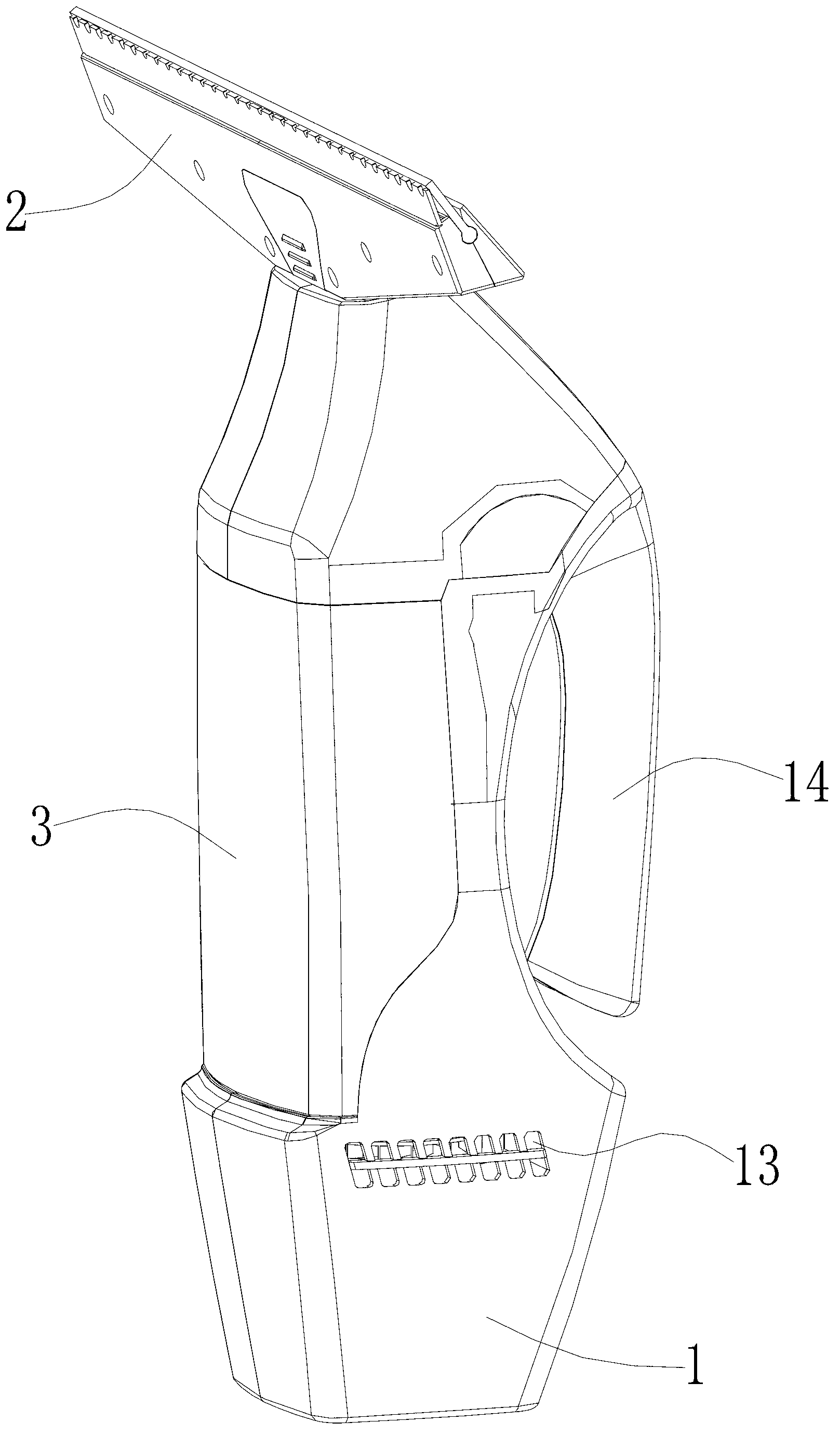
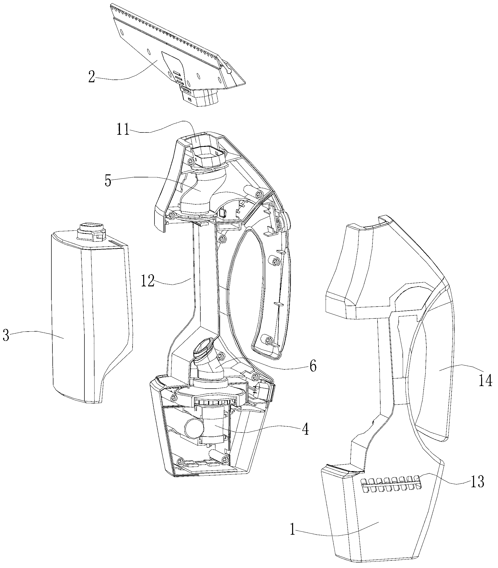
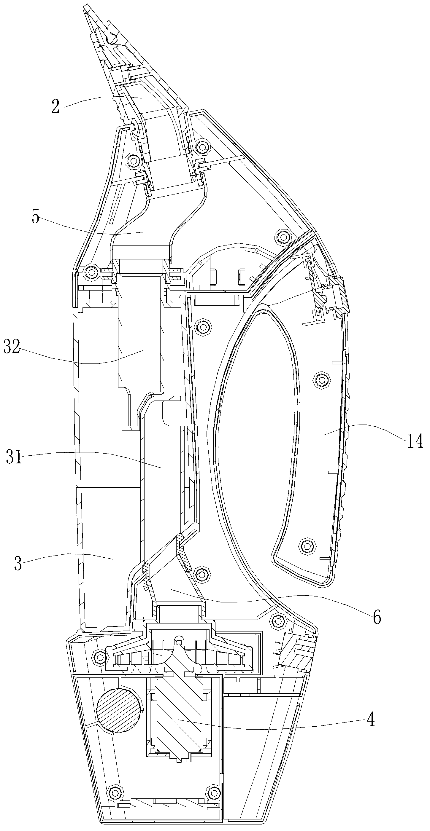
[0026] Such as Figures 1 to 4 As shown, a surface cleaning device at least includes a suction nozzle 2 , a water tank 3 , a suction unit 4 , a suction pipeline 5 , and a negative pressure pipeline 6 .

[0027] The suction nozzle 2 is used for sucking liquid and external air on the surface of the object when cleaning the surface of the object.

[0028] The water tank 3 has a cavity for collecting the sucked liquid.

[0029] The suction unit 4 is used to generate negative pressure and generate suction force.

[0030] The suction pipeline 5 is connected between the suction nozzle 2 and the water tank 3 , and is used for transporting the sucked liquid and external air into the water tank 3 .

[0031] The negative pressure pipeline 6 is connected between the suction unit 4 and the water tank 3 , and communicates with the suction pipeline 5 through the inner cavity of the water tank 3 .

[0032] The suction nozzle 2, the suction pipeline 5, the water tank 3, the negative pressur...


PUM


Abstract

A surface cleaning device comprises a suction nozzle, a water tank, a suction machine set, a suction pipeline and a negative pressure pipeline, wherein the suction nozzle is used for absorbing liquid on the surfaces of objects and outside air in the process of cleaning the surfaces of the objects; the water tank is provided with a cavity and used for collecting the absorbed liquid; the suction machine set is used for generating negative pressure and forming suction force; the suction pipeline is connected between the suction nozzle and the water tank and used for transporting the absorbed liquid and the outside air to the water tank; the negative pressure pipeline is connected between the suction machine set and the water tank and connected with an air path of the suction pipeline through the cavity inside the water tank. The surface cleaning device is characterized in that the suction nozzle, the suction pipeline, the water tank, the negative pipeline and the suction machine set are sequentially arranged from top to bottom; the liquid and the outside air absorbed by the suction nozzle enter the water tank along the same path through the suction pipeline from top to bottom; the liquid absorbed by the suction nozzle is collected by the water tank after entering the water tank; the outside air absorbed by the suction nozzle continues to flow along the path from top to bottom after entering the water tank and is exhausted by the suction machine set after passing through the negative pressure pipeline. The surface cleaning device is simple in structure, and can rapidly absorb the liquid on the surfaces of the objects and collect the liquid in the water tank.

Description

Technical field: [0001] The invention relates to a surface cleaning device, in particular to a cleaning device for the surface of a hard object. Background technique: [0002] When cleaning the surface of an object such as a glass surface, generally the glass surface is sprayed with a cleaning liquid, and then the glass surface is cleaned with a cleaning device. [0003] In order to simultaneously suck away the liquid on the glass surface in time when cleaning the surface of a hard object such as a glass surface, a patent with a publication number of CN101909499B discloses a portable hard surface suction device, but it has the following defects: 1. Because the liquid suction path is separated from the external air suction path, the suction force is weakened, and when the liquid and external air are sucked in and separated from water and gas by the water baffle, the liquid can only rely on itself The weight gets into the inside of the tank and the liquid cannot be pumped qui...

Claims


Application Information

Patent Timeline
IPC IPC(8): A47L1/08
CPCA47L1/05
Inventor 梁金然
Owner ZHONGSHAN JINSHUN HOUSEHOLD WARES
Learn More