Efficient ceramic core removal device for hollow blade

A ceramic core and hollow blade technology, which is applied in the field of hollow blade ceramic core removal equipment, can solve the problems of long time for core removal, complex inner cavity structure, ceramic core removal or low removal efficiency, and achieve faster The effect of removal speed

Active Publication Date: 2013-08-21
INST OF METAL RESEARCH - CHINESE ACAD OF SCI
View PDF4 Cites 21 Cited by
  • Summary
  • Abstract
  • Description
  • Claims
  • Application Information

AI Technical Summary

Benefits of technology

This new device removes ceramics from castings quickly with less damaging impact on their surfaces compared to previous methods like sandblast or water blast techniques. It uses small pieces made up mostly of silicon dioxide (SiO2) instead of larger ones used for other purposes such as aluminum oxynitride (AlON). These smaller Si02particles help remove faster than older methods while still being able to protect them during use.

Problems solved by technology

Technological Problem addressed by this patented method relates to removing ceramics from gas turbine engine components such as blade roots during manufacturing processes involving these materials. Current techniques involve either wetting them down into solvents containing strong bases (KOH) or adding an acid/alkali mixture before dissolving out any remaining material. These solutions have limitations when trying on complicated internal spaces like those involved in certain types of alloys. Additionally, there may also exist issues related to residual metal contaminants left behind after cleanup steps.

Method used


Image

  • Efficient ceramic core removal device for hollow blade
  • Efficient ceramic core removal device for hollow blade

Examples


Embodiment 1

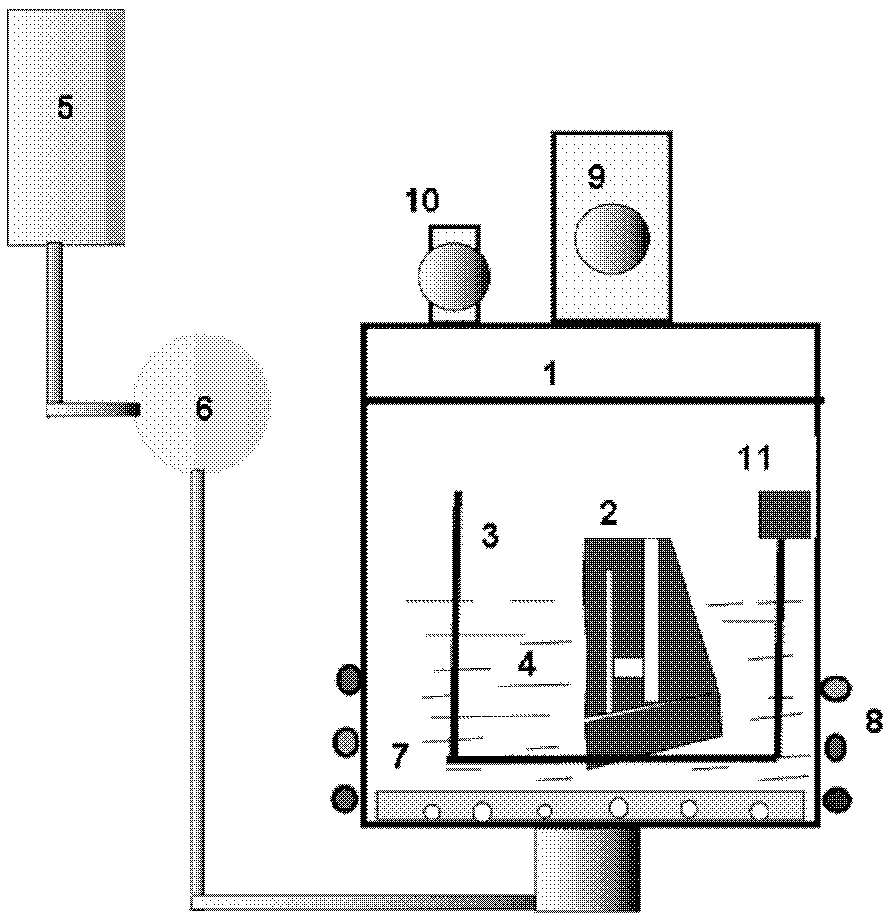
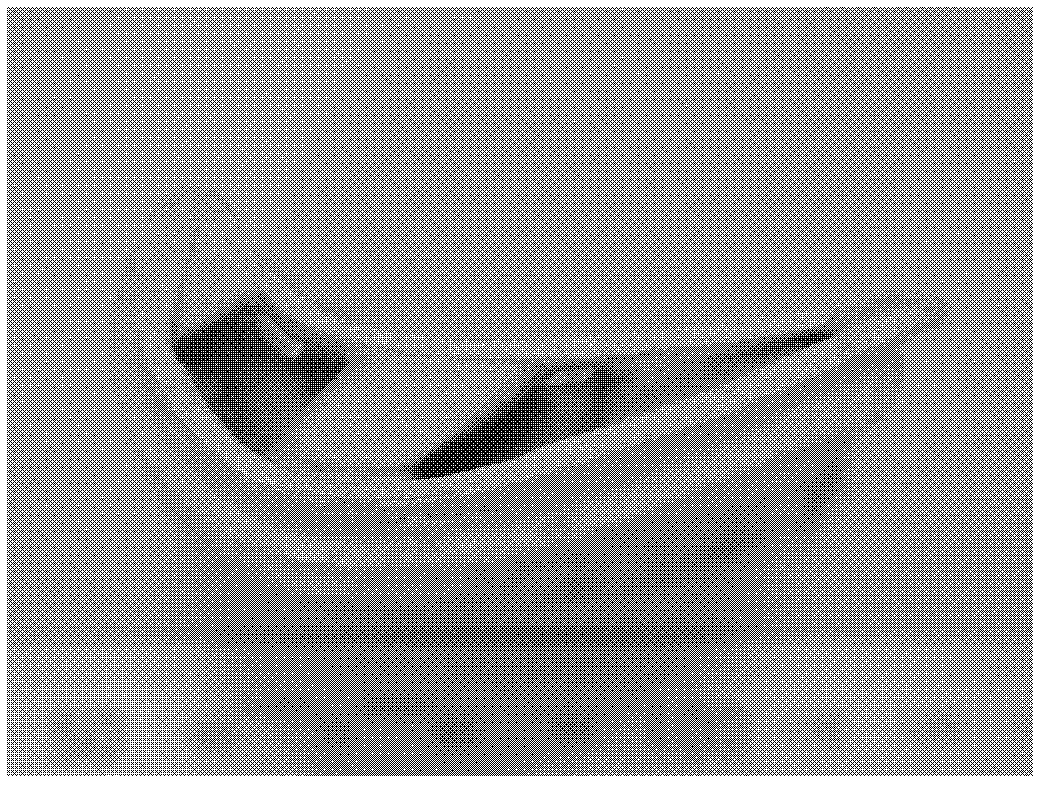
[0019] In the autoclave 1, the NaOH alkali solution 4 with a concentration of 30% is prepared, and the hollow blade 2 after casting is placed in the stainless steel basket 3 by using the lifting mechanism 11. The ceramic core for the blade is a silica-based ceramic core, which is resistant to alkali. Solution 4 is heated to a temperature of 250°C. At the same time, the pressure pump 5 is turned on to blow bubbles into the autoclave 1 for 30 minutes. When the pressure in the autoclave 1 rises to 4 atmospheres, the pressure is released. The valve 9 is depressurized to the normal pressure state, and then the above process is repeated 10 times. After the ceramic core is removed, the hollow blade 2 is synthesized with a hydrochloric acid solution with a concentration of 2-10% after the core is removed, and then cleaned with water. Hollow vane with ceramic core removed 2 see figure 2 .

[0020] Depend on figure 2 It can be seen that by adopting the equipment of the present inven...

Embodiment 2

[0022] In the autoclave 1, the KOH alkali solution 4 with a concentration of 35% is prepared, and the cast hollow blade 2 is placed in the stainless steel basket 3 by using the lifting mechanism 11. The ceramic core for the blade is a silica-based ceramic core, which is resistant to alkali. The solution 4 is heated, and the heating temperature is 170°C. At the same time, the air pressure pump 5 is turned on, and the air bubbles are blown into the autoclave 1 for 25 minutes. The pressure relief valve 9 releases the pressure to the normal pressure state, and then repeats the above process until the removal of the ceramic core is completed. After the blade is removed from the core, it is synthesized with a hydrochloric acid solution with a concentration of 3%, and then cleaned with water, and finally The casting after removing the core is obtained.

Embodiment 3

[0024] In the autoclave 1, the KOH alkali solution 4 with a concentration of 30% is prepared, and the cast hollow blade 2 is placed in the stainless steel basket 3 by using the lifting mechanism 11. The ceramic core for the blade is a silica-based ceramic core, which is resistant to alkali. The solution 4 is heated, and the heating temperature is 230°C. At the same time, the air pressure pump 5 is turned on, and the air bubbles are blown into the autoclave 1 for 20 minutes. The pressure relief valve 9 releases the pressure to the normal pressure state, and then repeats the above process until the removal of the ceramic core is completed. After the blade is removed from the core, it is synthesized with a hydrochloric acid solution with a concentration of 3%, and then cleaned with water, and finally The casting after removing the core is obtained.


PUM


Abstract

The invention provides a ceramic core removal device which mainly structurally comprises a high-pressure reaction vessel 1, a stainless steel basket 3, a pressure pump 5, an air storage chamber 6, a foam disk 7, heating elements 8, a pressure release valve 9, a safety valve 10 and a lifting mechanism 11. In the use process of the ceramic core removal device, a large number of tiny bubbles are blown into an alkali solution 4 in a pressurizing manner and penetrate through various pores in a hollow blade 2 to reach a deep position of a ceramic core, a reaction product rapidly diffuses into the alkali solution by the high-speed scouring action of the bubbles on a solid-liquid interface reaction layer, contact of the alkali solution and the ceramic core is constantly ensured, normal reaction is ensured, and removal of the ceramic core is greatly accelerated.

Description


Claims


Application Information

Patent Timeline
Owner INST OF METAL RESEARCH - CHINESE ACAD OF SCI
Why Eureka
Try Eureka