
Microbial dredging device

A dredging device and microbial technology, applied in the field of microbial dredging devices, can solve problems such as unsatisfactory dredging effect, achieve ideal removal effect, easy installation, and reduce friction coefficient.

Active Publication Date: 2019-04-05
郭山河
View PDF6 Cites 5 Cited by
  • Summary
  • Abstract
  • Description
  • Claims
  • Application Information

AI Technical Summary

Problems solved by technology

[0003] The purpose of the present invention is to provide a microbial dredging device, which has the advantages of good dredging effect and solves the problem of unsatisfactory dredging effect of common microbial dredging devices

Method used


Image

  • Microbial dredging device
  • Microbial dredging device
  • Microbial dredging device

Examples


no. 1 approach

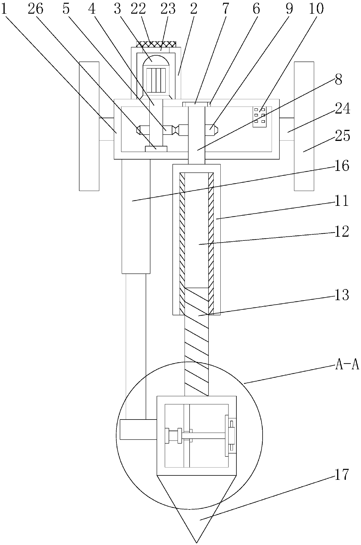
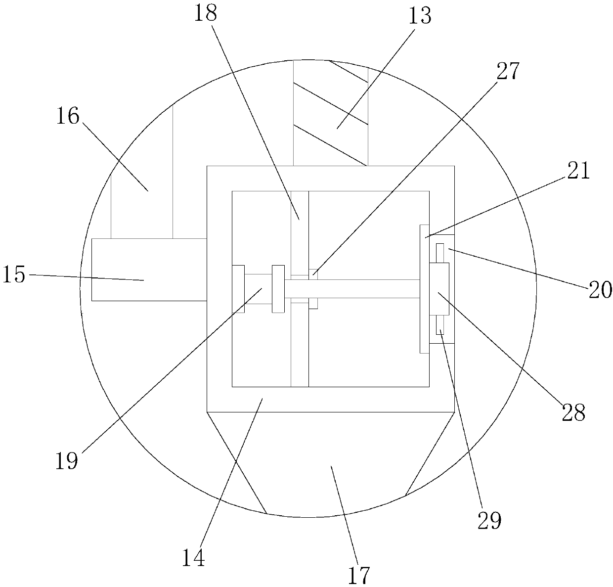
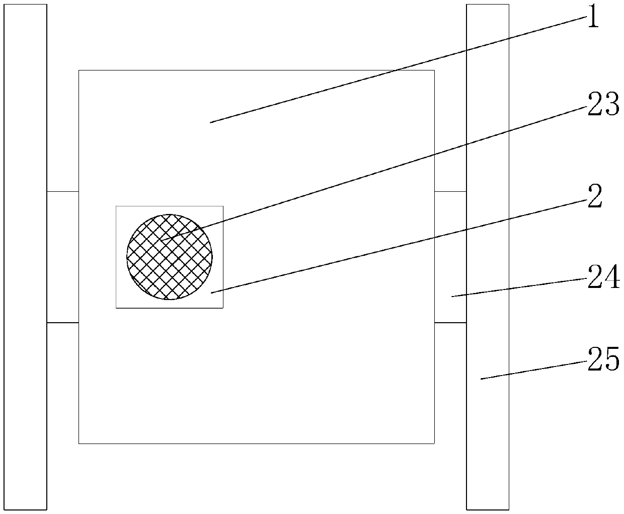
[0019] First implementation: see Figure 1-3 , a microbial dredging device, comprising a shell 1, the top of the shell 1 is fixedly connected to the organic shell 2, the left and right sides of the shell 1 are fixedly connected with a fixed block 24, and the fixed block 24 is away from the side of the shell 1 Fixedly connected with a mounting plate 25, through the mutual cooperation of the fixed block 24 and the mounting plate 25, the effect of facilitating installation is played. A vent 22 is provided, and the driving motor 3 is cooled by setting the vent 22. The top of the casing 2 is provided with a dust-proof net 23 that is compatible with the vent 22, and the dust-proof net 23 is set to Dust-proof effect, the output shaft of the drive motor 3 is fixedly connected with the drive shaft 4, the bottom end of the drive shaft 4 penetrates the housing 1 and extends to its interior, the surface of the drive shaft 4 inside the housing 1 is fixedly connected with the second A gear...

no. 2 approach

[0022] Second embodiment: as shown in claim 1, a microbial dredging device includes a casing 1, the top of the casing 1 is fixedly connected to the organic casing 2, and the top of the casing 1 is located in the casing 2 A drive motor 3 is fixedly connected to the inside of the drive motor 3, and a drive shaft 4 is fixedly connected to the output shaft of the drive motor 3. The bottom end of the drive shaft 4 penetrates the housing 1 and extends to its interior. The drive located inside the housing 1 The surface of the rotating shaft 4 is fixedly connected with the first gear 5, the top of the inner wall of the housing 1 and the right side of the first gear 5 are provided with a fixed groove 6, and the inner wall of the fixed groove 6 is fixedly connected with a rolling bearing 7, so The bottom of the rolling bearing 7 is movably connected with a rotating shaft 8, the surface of the rotating shaft 8 is fixedly connected with a second gear 9, the first gear 5 and the second gear...


PUM


Abstract

The invention discloses a microbial dredging device, comprising a casing body. The top of the casing body is fixedly connected with a shell, and the top of the casing body is fixedly connected with adriving motor inside the shell. The microorganism is placed in the inner part of the box through the coordination of a driving motor, a driving shaft, a first gear, a rolling bearing, a rotating shaft, a second gear, a controller, a thread sleeve, a thread groove, a threaded rod, a box, a telescopic rod, a drill bit, a cylinder, a through groove and a baffle plate. The controller drives the driving shaft forward or backward by controlling the driving motor, the driving shaft drives the second gear to rotate through the first gear, and the second gear drives the thread sleeve to rotate throughthe rotating shaft. Due to the screw principle, the threaded rod drives the box to move upward or downward, and the microorganism can be applied to the mud at different depth positions. The speed of sludge removal is accelerated, and the sludge removal effect is ideal, which brings great convenience to the dredging work.

Description

technical field [0001] The invention relates to the technical field of microbial dredging, in particular to a microbial dredging device. Background technique [0002] Silt has increasingly affected the normal performance of various functions such as flood control, drainage, irrigation, water supply, and navigation. A large amount of sediment is deposited in natural or artificial water bodies every year, and nutrients, heavy metals, and other pollutants in the water are constantly deposited in the silt. Enrichment, the pollutants in the sludge are several orders of magnitude higher than the water body. Although many cities are now carrying out sewage treatment, if the endogenous pollution of the sludge is not removed, the pollutants in the sludge will continue to be released into the water body, and the water will continue to be polluted repeatedly. In order to restore the normal function of the water body, dredging works are urgently needed. Dredging belongs to water conser...

Claims


Application Information

Patent Timeline
IPC IPC(8): C02F11/02
CPCC02F11/02
Inventor 胡奕清
Owner 郭山河
Learn More