Liquid spray head and manufacturing method thereof

A technology of liquid nozzles and manufacturing methods, which is applied in printing and other directions, and can solve problems such as high manufacturing costs, low yield of liquid nozzles, and low printing quality

Active Publication Date: 2013-08-21
ZHUHAI SAILNER 3D TECH CO LTD
View PDF19 Cites 13 Cited by
  • Summary
  • Abstract
  • Description
  • Claims
  • Application Information

AI Technical Summary

Problems solved by technology

[0008] The invention provides a liquid nozzle and its manufacturing method to solve the technical p

Method used


Image

  • Liquid spray head and manufacturing method thereof
  • Liquid spray head and manufacturing method thereof
  • Liquid spray head and manufacturing method thereof

Examples


Embodiment Construction

[0045] Following will describe the present invention in detail by embodiment:

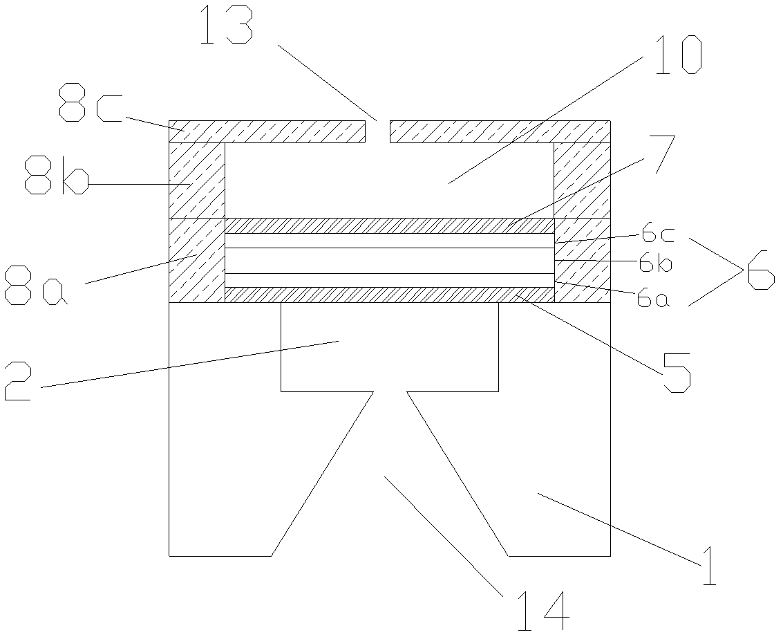
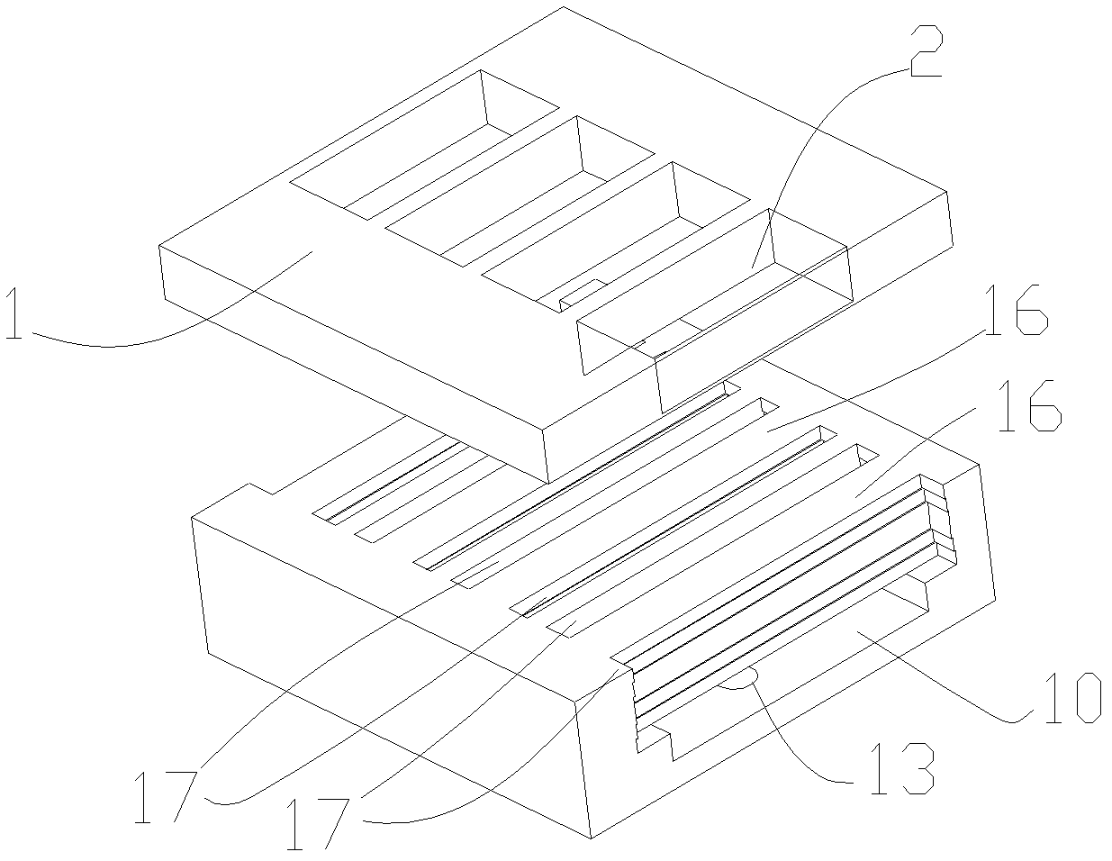
[0046] figure 1 and figure 2They are respectively a sectional view and a perspective view of a liquid ejection head according to an embodiment of the present invention. As shown in the figure, a liquid ejection head includes: a silicon substrate 1; several polymer film layers arranged on the surface of the silicon substrate, and a piezoelectric element thin film layer 6a / 6b / 6c, nozzle orifice film layer 8c; the part of the several polymer film layers at the position of the liquid chamber, that is, the liquid chamber polymer film layer 8a / 8b forms the liquid chamber 10, the piezoelectric element 6 and the The nozzle hole 13 is formed at the part of the number of polymer film layers at the position of the nozzle hole 13; the piezoelectric element 6 is formed by the lower electrode 6a, the piezoelectric layer 6b and the lower electrode 6c formed by the piezoelectric element film layer, and the pie...


PUM


Abstract

The invention relates to a liquid spray head and a manufacturing method of the liquid spray head. The liquid spray head comprises a silicon substrate, a liquid cavity, a two-end supported beam piezoelectric element, an ink supply channel and a nozzle hole, wherein the liquid cavity is arranged on the surface of the silicon substrate, the two-end supported beam piezoelectric element is arranged in the liquid cavity, two ends of the two-end supported beam piezoelectric element are fixed, the ink supply channel is arranged on the silicon substrate, and the nozzle hole is communicated with the liquid cavity. The liquid cavity and the nozzle hole are jointly formed by one or more polymer film layers arranged on the surface of the silicon substrate. The polymer film layers are easy to process, are not easy to break, and are integrally formed in manufacturing. Products which are high in efficiency, high in precision, and low in cost can be obtained, so that a high-density liquid spray head of a two-end supported beam structure is manufactured with high precision at a low cost. The technical problem that an existing liquid spray head is low in rate of finished products, high in manufacturing cost, and low in print quality is solved.

Description

technical field [0001] The invention relates to a liquid spray head and a manufacturing method thereof. Background technique [0002] Existing nozzles that use piezoelectric elements as actuators to eject ink mainly include the following three types. One is that the piezoelectric element and the vibrating plate part form a pressure chamber that communicates with the nozzle hole corresponding to the ink droplet. The deformation of the electric element and the vibrating plate causes the volume of the pressure chamber to change, thereby ejecting the ink from the nozzle hole. Because the volume change of the pressure chamber is required, the deformation of the piezoelectric element and the vibration plate needs to be large, the deformation energy of the piezoelectric element needs to be large enough, and the side wall of the pressure chamber needs good strength and toughness, so in order to obtain The size of the ejected ink droplets required, the piezoelectric element needs a ...

Claims


Application Information

Patent Timeline
IPC IPC(8): B41J2/14B41J2/16
Inventor 周毅李越
Owner ZHUHAI SAILNER 3D TECH CO LTD
Why Eureka
Try Eureka