System and method for injecting fuel

A fuel and pre-injection technology, which is applied in the field of fuel injection systems and methods, can solve problems such as not being within the ideal range, and achieve the effect of avoiding gradual conversion and reducing the amount of time

Inactive Publication Date: 2013-08-21
FORD GLOBAL TECH LLC
View PDF11 Cites 11 Cited by
  • Summary
  • Abstract
  • Description
  • Claims
  • Application Information

AI Technical Summary

Problems solved by technology

However, if the number of pilot fuel injections is changed when the number of fuel injections is changed, and th

Method used


Image

  • System and method for injecting fuel
  • System and method for injecting fuel
  • System and method for injecting fuel

Examples


Example Embodiment

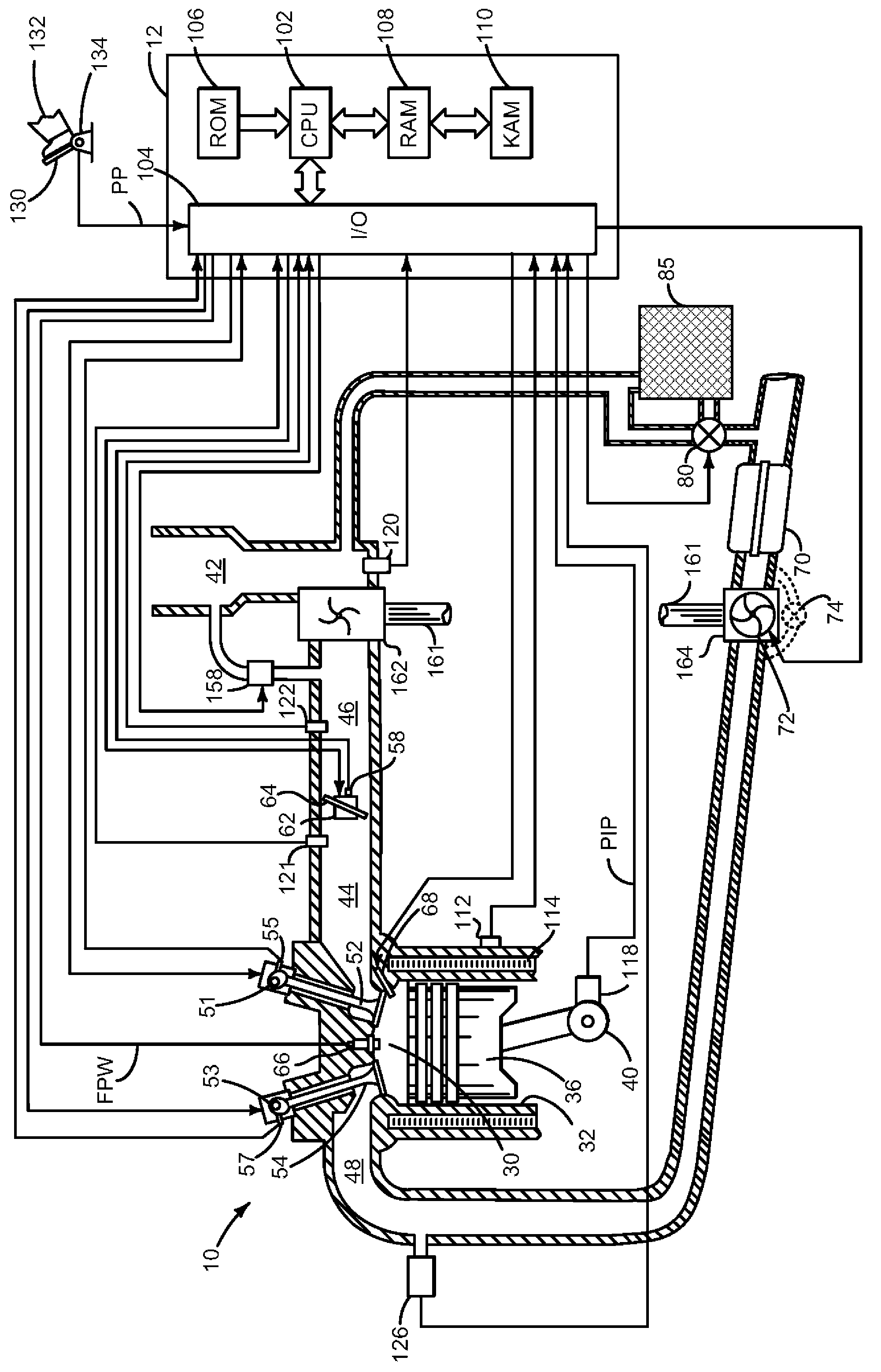
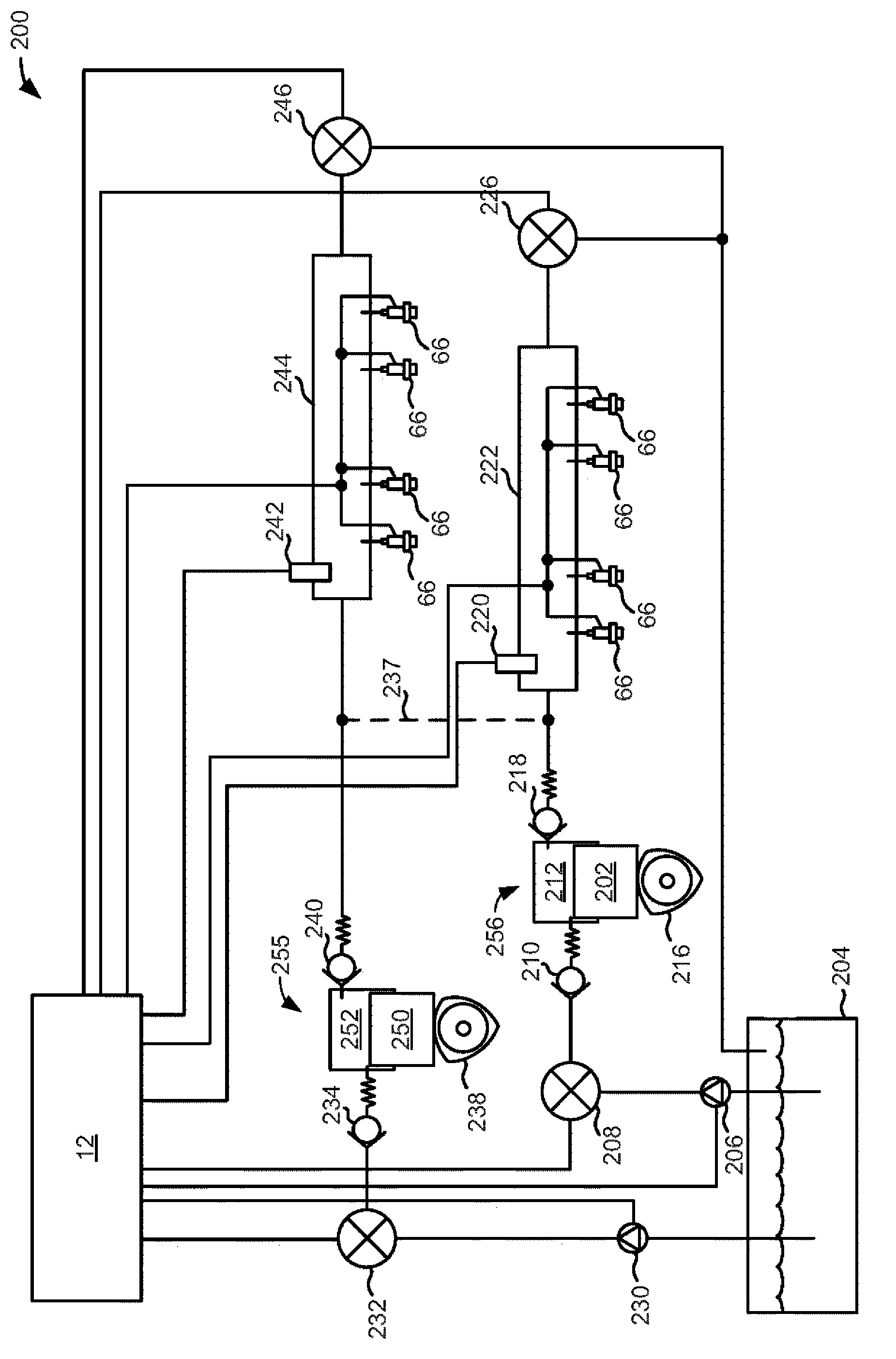
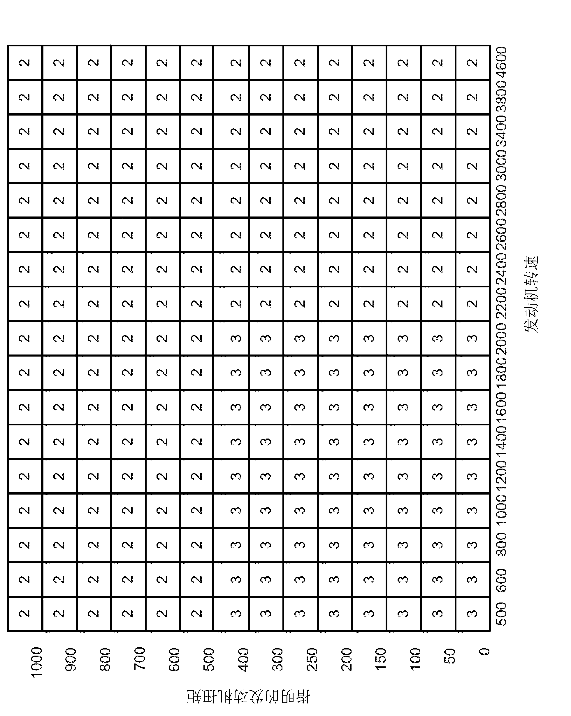
[0028] The invention relates to compensating for changes in the number of pilot fuel injections delivered to a cylinder during a cylinder cycle. figure 1 An example of a supercharged diesel engine is shown, where Figure 10 A method to adjust the number of pilot fuel injections and fuel pressure to improve engine emissions and / or reduce combustion noise. figure 2 An example fuel delivery system for an engine with two cylinder banks is shown. image 3 An example map of pilot fuel injection is shown. Figure 4-5 and Figure 8-9 An example of fuel pressure adjustment in response to the number of pilot fuel injection pulses is shown. Image 6 and 7 An example cylinder layout and firing order with two cylinder banks is shown. at last, Figure 10 is a flowchart of an example method of adjusting fuel pressure and an amount of pilot fuel injection supplied to cylinders of an engine.

[0029] see figure 1 , an internal combustion engine 10 comprising a plurality of cylinders i...


PUM


Abstract

Methods and systems for adjusting fuel injection of an internal combustion engine are disclosed. In one example, a change in fuel pressure is scheduled when a number of pilot fuel injections provided by a fuel injector to a cylinder transitions from a first number during a first engine cycle to a second number during a second engine cycle. The methods and systems may reduce engine emissions and improve engine noise characteristics.

Description

technical field [0001] This specification relates to injecting fuel into an internal combustion engine. In one example, a method of adjusting fuel pressure along with the number of pilot fuel injections is disclosed. This method is particularly useful for compression ignition engines. Background technique [0002] Combustion in diesel engines is facilitated by compressing an air-fuel mixture within the engine cylinders. When the air-fuel mixture is compressed, the temperature and pressure within the cylinder rise so that the air-fuel mixture ignites without an externally provided ignition source, such as a spark plug. Ignition of the air-fuel mixture releases heat and increases temperature and pressure within the cylinder. Depending on conditions, engine combustion may increase engine noise and reduce driver satisfaction. [0003] One approach to addressing combustion noise is to provide pilot injection of fuel during the cylinder cycle. A pilot fuel injection into the ...

Claims


Application Information

Patent Timeline
IPC IPC(8): F02D41/30
CPCF02D41/3017F02D41/3845F02D41/403Y02T10/40
Inventor J·P·斯泰容
Owner FORD GLOBAL TECH LLC
Why Eureka
Try Eureka