Impedance-based adjustment of power and frequency

A technique of frequency value, plasma, applied in the field of computer programs to solve the problem of impedance matching not fast enough to respond, unable to adjust power and/or frequency plasma, etc.

Active Publication Date: 2013-09-11
LAM RES CORP
View PDF6 Cites 8 Cited by
  • Summary
  • Abstract
  • Description
  • Claims
  • Application Information

AI Technical Summary

Problems solved by technology

However, in some cases impedance matching cannot be fast enough to respond to changes in plasma impedance
[0004] Also, while some systems are quick enough to respond to this change, these systems may not be able to precisely adjust power and / or frequency to stabilize the plasma

Method used


Image

  • Impedance-based adjustment of power and frequency
  • Impedance-based adjustment of power and frequency
  • Impedance-based adjustment of power and frequency

Examples


Embodiment Construction

[0034] The following embodiments illustrate systems and methods for impedance-based adjustment of power and frequency. It will be apparent that the present embodiments may be practiced without some or all of these specific details. In other instances, well known process operations have not been described in detail in order not to unnecessarily obscure the present embodiments.

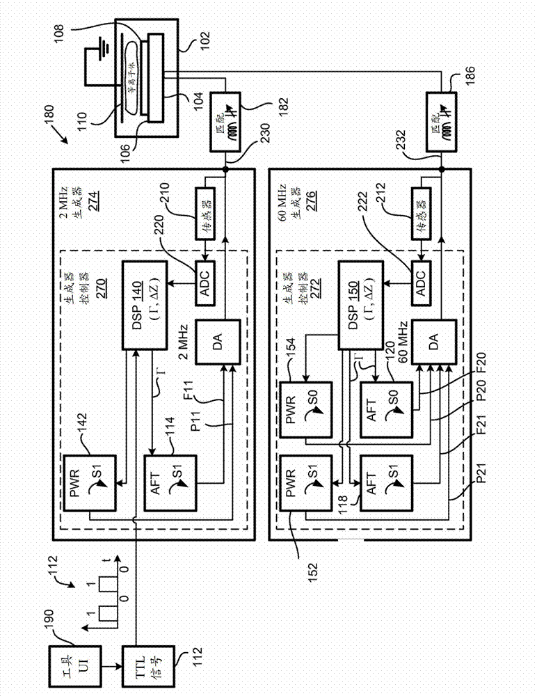
[0035] figure 1 is a block diagram of an embodiment of a system 180 for changing state based on plasma impedance. A 2 megahertz (MHz) radio frequency (RF) driver amplifier (DA) system supplies RF power to the lower electrode 104 of the plasma chamber 102 via an impedance matching circuit 182 . Similarly, a 60 MHz DA system supplies RF power to the lower electrode 104 via the impedance matching circuit 186 . It should be noted that in one embodiment, instead of using a 60 MHz source, a 27 MHz source is used to provide RF power to the lower electrode 104 . Also, it should be noted that the values ​​2M...


PUM


Abstract

The invention relates to systems and methods for impedance-based adjustment of power and frequency. A system includes a plasma chamber for containing plasma. The plasma chamber includes an electrode. The system includes a driver and amplifier coupled to the plasma chamber for providing a radio frequency (RF) signal to the electrode. The driver and amplifier is coupled to the plasma chamber via a transmission line. The system further includes a selector coupled to the driver and amplifier, a first auto frequency control (AFC) coupled to the selector, and a second AFC coupled to the selector. The selector is configured to select the first AFC or the second AFC based on values of current and voltage sensed on the transmission line.

Description

technical field [0001] The present embodiments relate to improving the response time to changes in plasma impedance and / or increasing the accuracy of stabilizing the plasma, and more particularly to apparatus, methods and computer programs for impedance-based adjustment of power and frequency. Background technique [0002] In some plasma processing systems, multiple radio frequency (RF) signals are provided to one or more electrodes within the plasma chamber. The RF signal assists in generating plasma within the plasma chamber. Plasmas are used for various operations such as cleaning substrates placed on electrodes underneath, etching substrates, etc. [0003] An impedance matching circuit is usually placed between the driver and amplifier system that generates the radio frequency (RF) signal and the plasma chamber. The impedance matching circuit matches the impedance of the load (eg, the plasma within the plasma chamber) to the impedance of the source (eg, the driver ampl...

Claims


Application Information

Patent Timeline
Patent Type & Authority Applications(China)
IPC IPC(8): H01J37/32
CPCH01J37/32082H01J37/32174H01J37/32183H01J37/32935H01J37/32981H01J37/32146H01J37/32165H01J37/3299H01L21/3065H03H7/40H05H1/46
Inventor 约翰·C·小瓦尔考布拉德福德·J·林达克
Owner LAM RES CORP
Why Eureka
Try Eureka