
Display device and method for driving display device

A display device and a technology for displaying signals, which are applied in static indicators, instruments, etc., can solve the problems of increasing the amount of time, the signal is easily affected by external noise or signal deterioration, and the writing current value of the display panel is low.

Inactive Publication Date: 2005-12-14
SOLAS OLED LTD
View PDF0 Cites 7 Cited by
  • Summary
  • Abstract
  • Description
  • Claims
  • Application Information

AI Technical Summary

Problems solved by technology

[0010] However, as mentioned above, in particular, charging and discharging operations of current supply in signal wiring require a certain amount of time; The current value of the write current supplied to the display panel becomes lower
It has disadvantages in that the amount of time required in the charge and discharge operation of the signal wiring increases, rate control of the operation speed of the data driver due to the rate of the charge and discharge operation must be performed, and ideal image quality is realized become more difficult
However, since the write current is an analog signal that changes according to the light-generating state of the light-emitting element, the signal is easily affected by external noise or signal deterioration, which produces a reduction or change in the light-generating luminosity in the light-emitting element
This problem makes it difficult to obtain a stable image display with an appropriate level of luminosity

Method used


Image

  • Display device and method for driving display device
  • Display device and method for driving display device
  • Display device and method for driving display device

Examples


no. 1 example

[0086] First, a first embodiment of a current generating circuit in a display device related to the present invention will be explained with reference to the drawings.

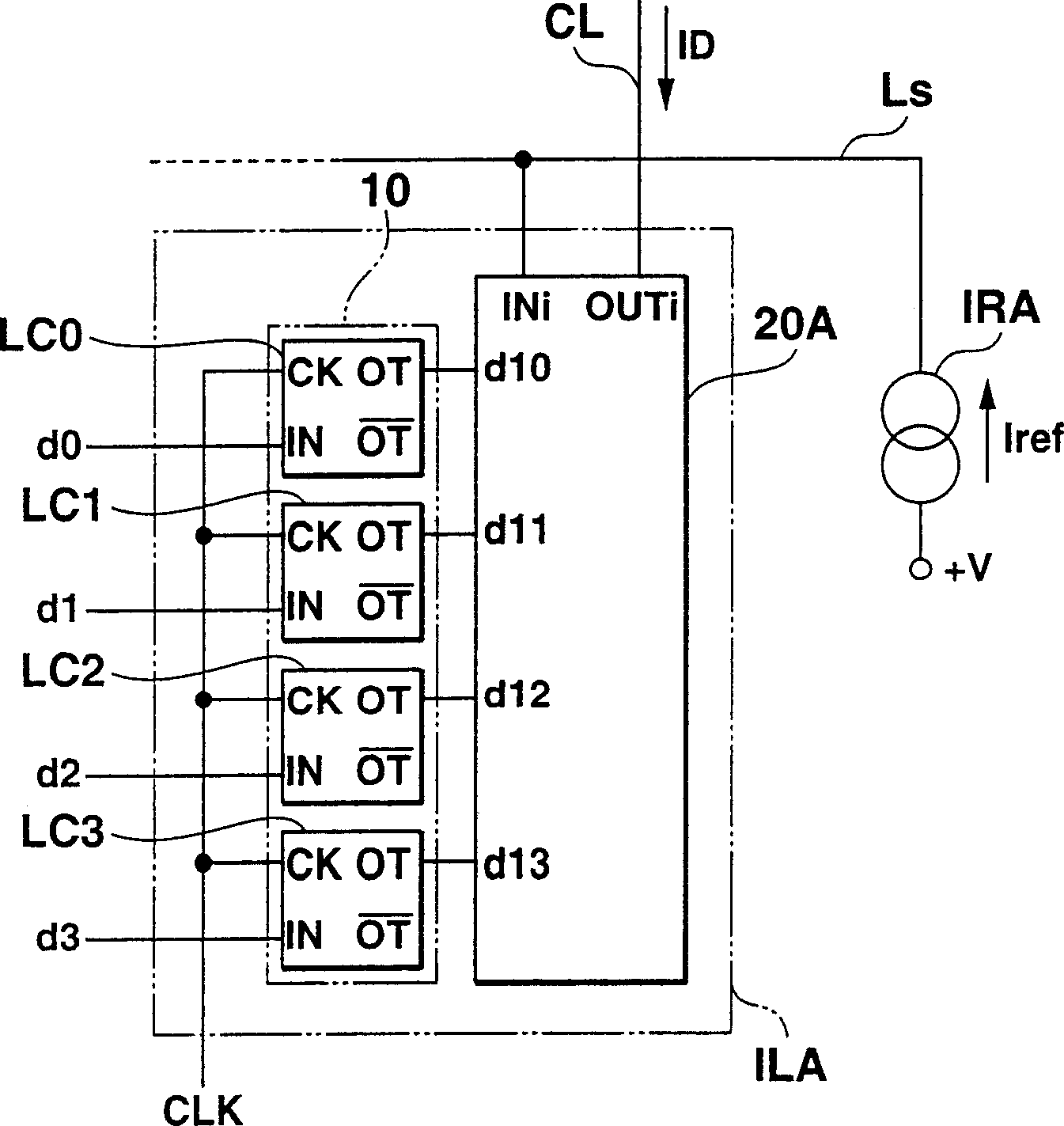
[0087] figure 1 is an outline block diagram showing a first embodiment of a current generating circuit in a display device related to the present invention.

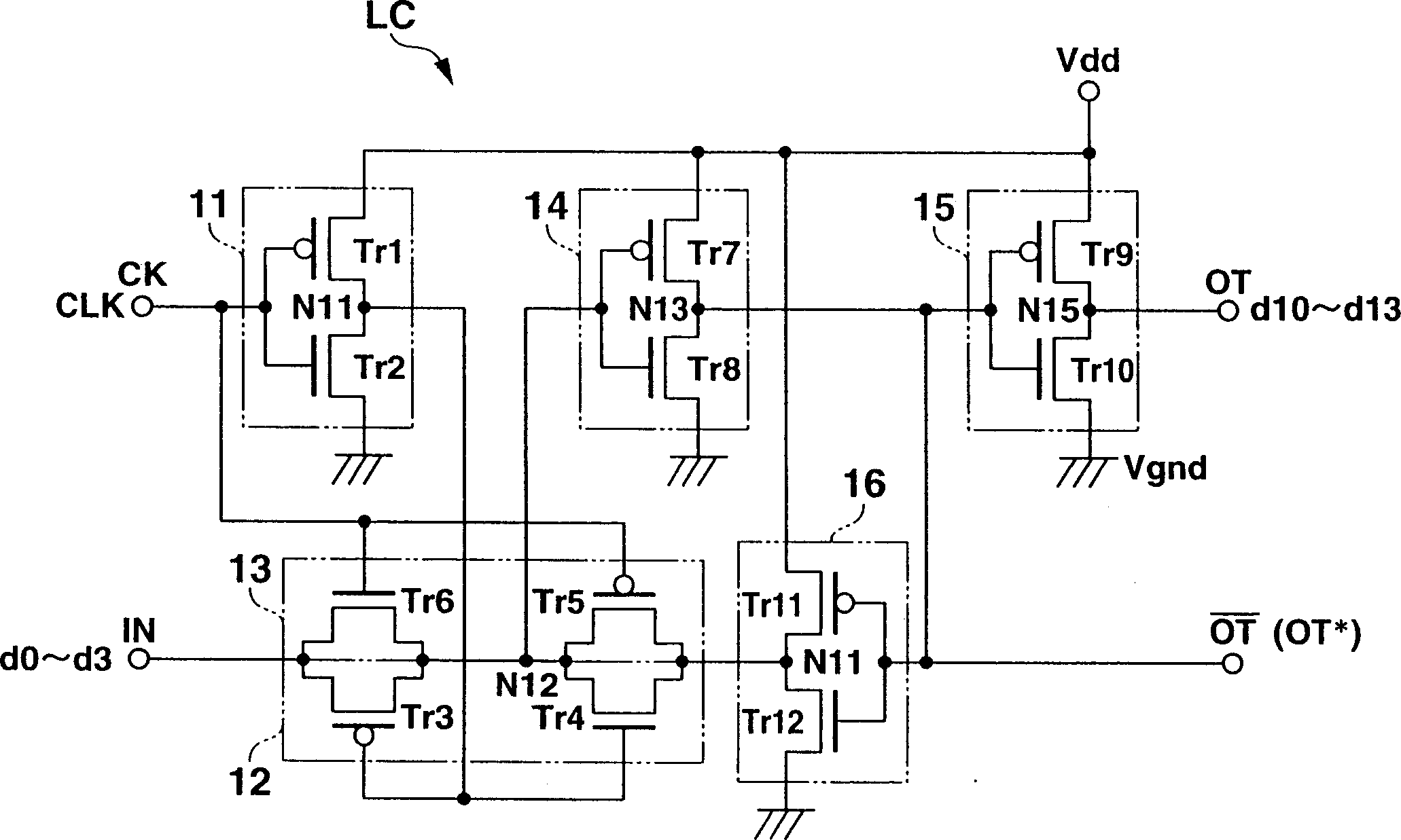
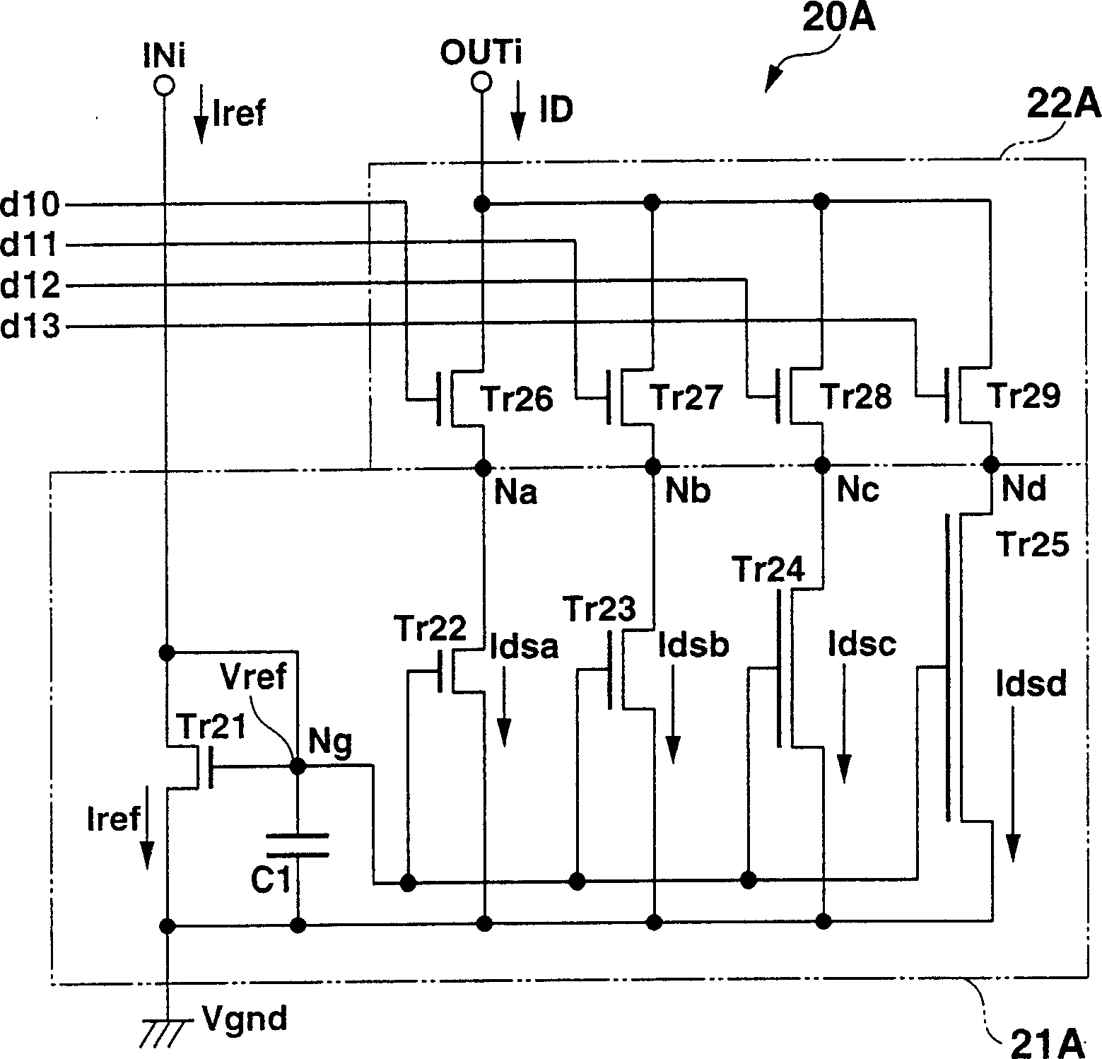
[0088] Such as figure 1 As shown, the current generating circuit ILA related to this embodiment has a configuration formed of a signal latch section 10 (signal holding circuit) and a current generating section 20A. The signal latch section 10 includes latch circuits LC0, LC1, LC2, and LC3 (LC0-LC3), each of which receives a number for specifying a plurality of bits (a case of four bits is shown in this embodiment) for specifying a current value. Signals d0, d1, d2, and d3 (d0-d3) and holds them (latches one or more, as the case may be). The current generation section 20A outputs to the load current supply line CL connected to the load, which receives ...


PUM


Abstract

The display device includes: a display panel including a plurality of signal lines (DL) and a plurality of scanning lines (SL) crossing each other at right angles, and an optical element (OEL) arranged near intersections of the plurality of signal lines and scanning lines A plurality of display pixels (EM); a signal drive circuit (130A-G), with a plurality of current generation circuits (ILA, ILB, ISA, ISB, ISC-F, PXA-D); the current generation circuit includes a drive current generation circuit ( 22A-D), for generating a driving current according to multiple levels of current based on the value of the display signal provided to each scanning line; the scanning driving circuit (120A, 120B), for sequentially applying the scanning signal to each signal line, In order to set the selection state of each display pixel in each line period; the gradation current generating circuit (21A-D) is used for generating a plurality of gradation currents according to each display signal bit based at least on a constant predetermined reference current.

Description

technical field [0001] The present invention relates to a display device for displaying desired image information on a display panel including a plurality of display pixels having a current-driven optical element, and more particularly, to a display device and a method of driving the display device. Background technique [0002] In recent years, personal computers and visual device monitors with electronic screens called cathode ray tubes (CRTs) are rapidly becoming Gotta be outdated. In particular, LCDs are becoming common because they offer many practical advantages over other display technologies. LCDs are thinner, lighter and consume far less power than traditional CRTs. LCDs are found everywhere in our daily lives, from large-screen televisions to small laptop computers and personal digital assistants (PDAs) and even smaller cell phones, digital cameras and many other electronic devices, in all shapes and sizes Appear. [0003] As next-generation display devices (di...

Claims


Application Information

Patent Timeline
Patent Type & Authority Applications(China)
IPC IPC(8): G09G3/325G09G3/3275G09G3/3283
Inventor 两泽克彦白崎友之
Owner SOLAS OLED LTD
Learn More