System for determining egr cooler degradation

一种EGR冷却器、劣化的技术,应用在装料系统、机器/发动机、燃料中加入非燃料物质等方向,能够解决不能物理系统相容、很难确定提取、EGR系统模型大校准时间等问题,达到简化诊断、减少时间量的效果

Active Publication Date: 2012-11-21
FORD GLOBAL TECH LLC
View PDF8 Cites 11 Cited by
  • Summary
  • Abstract
  • Description
  • Claims
  • Application Information

AI Technical Summary

Problems solved by technology

However, the EGR system model may require significant calibration time and may not be well compatible with the physical system during some operating conditions
For example, the EGR temperature estimate may not fit the measured EGR temperature shortly after opening the EGR bypass valve to allow cooled EGR to flow to the engine intake system because it may be difficult to determine when untreated exhaust gas is flowing to the engine How much heat has been extracted from the exhaust in the EGR cooler while the intake manifold

Method used


Image

  • System for determining egr cooler degradation
  • System for determining egr cooler degradation
  • System for determining egr cooler degradation

Examples


Embodiment Construction

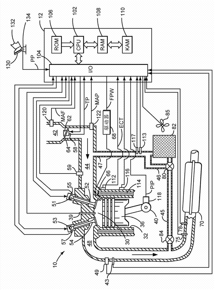
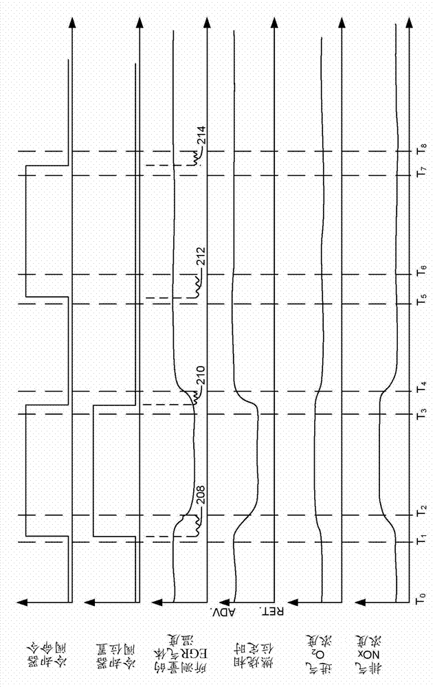
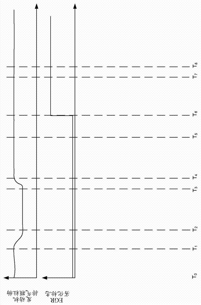
[0021] This instruction deals with diagnosing deterioration of the EGR system. In one example, the EGR system is adapted for diesel engines such as figure 1 shown. However, this instruction can also provide benefits for gasoline and alternative fuel engines. Accordingly, the present disclosure is not limited to a particular type of engine or a particular EGR system configuration. Figure 2-3 shows when the engine and EGR system are based on Figure 4 The analog signal of interest to the method runtime.

[0022] refer to figure 1 , the internal combustion engine 10 includes a plurality of cylinders, one of which is as figure 1 As shown, it is controlled by the engine electronic controller 12. Engine 10 includes combustion chamber 30 and cylinder walls 32 with piston 36 positioned therein and connected to crankshaft 40 . Combustion chamber 30 is shown communicating with intake manifold 44 and exhaust manifold 48 via respective intake valve 52 and exhaust valve 54 . Ea...


PUM


Abstract

Systems and methods for diagnosing an EGR system are presented. The method provides for indicating EGR system degradation in response to a temperature at an outlet of an EGR cooler. The method may require less calibration effort than a model based diagnostic.

Description

technical field [0001] The present description relates to methods and systems for improving operation and diagnostics of exhaust gas recirculation (Exhaust Gas Recirculation, EGR) systems. This approach may be particularly useful for engines with cooled EGR. Background technique [0002] Engines may include EGR to help reduce engine emissions and improve engine efficiency. In some systems, the EGR may be cooled by a cooler in communication with the engine exhaust passage and the engine intake manifold. The EGR system may further include a bypass valve for directing EGR about the EGR cooler such that EGR is directed from the exhaust passage to the engine intake manifold. Therefore, the EGR system can provide cooled or exhaust temperature EGR gas to the engine according to the engine operating state to improve engine emissions and fuel economy. However, during some conditions it is possible to degrade the EGR cooler and / or the EGR cooler bypass valve. For example, it is po...

Claims


Application Information

Patent Timeline
Patent Type & Authority Applications(China)
IPC IPC(8): F02M25/07
CPCF02M25/073F02M25/0754F02D2041/0067F02M25/0738Y02T10/121F02M25/0702F02M25/0728F02M26/49F02M26/25F02M26/27F02M26/47F02M26/33
Inventor 金雍华迈克尔·J·文·尼乌斯达特埃里克·库尔茨
Owner FORD GLOBAL TECH LLC
Why Eureka
Try Eureka