Elastic locking device
A locking device and elastic technology, applied in the direction of fluid pressure actuators, brake types, mechanical equipment, etc., can solve the problems of increased clamping force, low bearing capacity, poor rigidity, etc., to achieve increased clamping force, Improve the bearing capacity and enhance the rigidity of the machine
- Summary
- Abstract
- Description
- Claims
- Application Information
AI Technical Summary
Problems solved by technology
Method used
Image
Examples
Embodiment 1
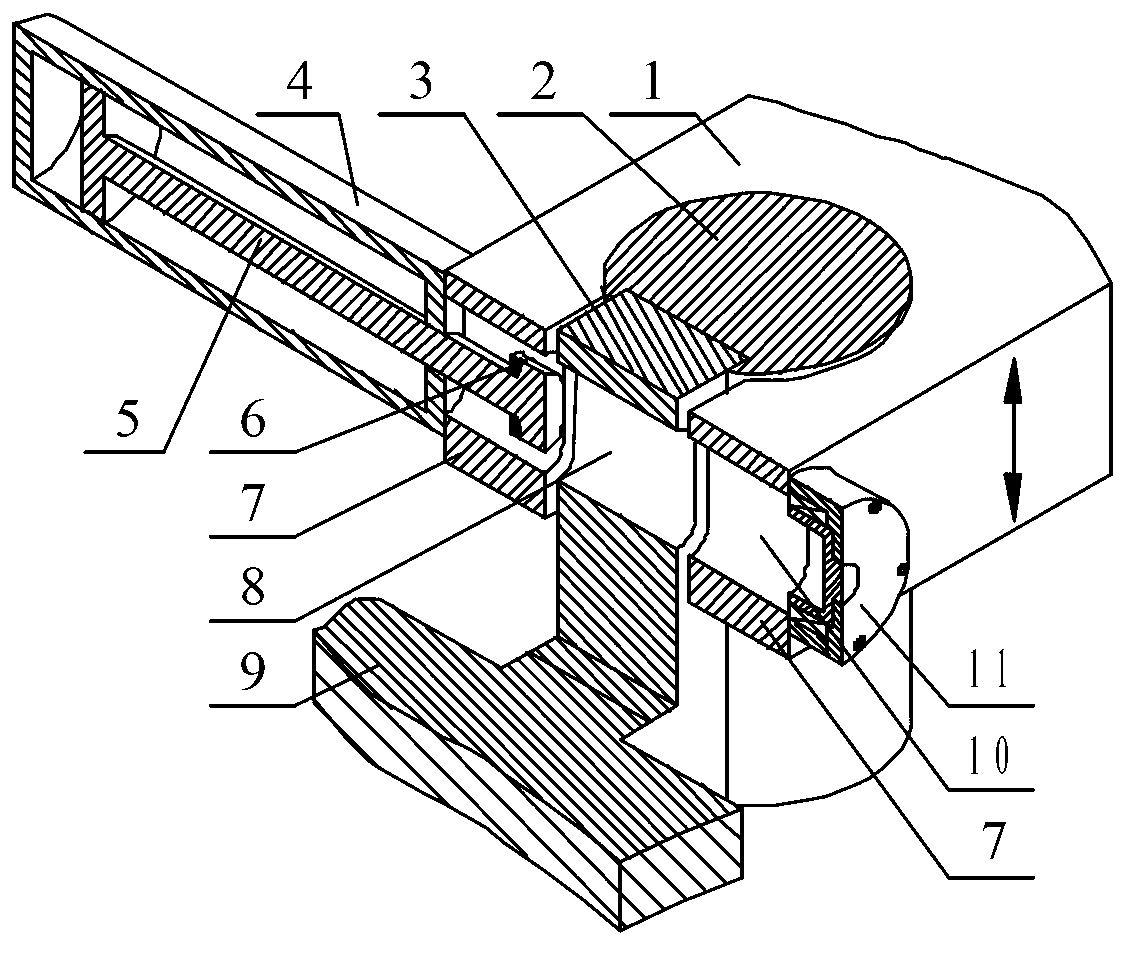
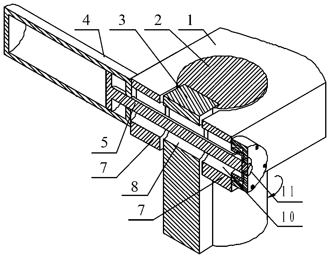
[0031] An elastic locking device of the present invention includes a non-full cylinder 2, an elastic clamp flap 7 on the moving beam 1 and a hydraulic cylinder clamping mechanism 4, and the non-full cylinder 2 is fixed to the side column 9 through a rectangular section member 3. Connected together, the movable crossbeam 1 is provided with an open round hole, and the open round hole is in clearance fit with the non-integral cylinder 2, and the two ends of the opening of the round hole are used as two elastic clips 7 of the movable crossbeam 1 The opening formed by the two elastic clips 7 leaves a certain gap margin with the rectangular section member 3, so that when the distance between the two elastic clips 7 is reduced to realize the clamping process of the non-integral cylinder 2, the two There is always a gap between the elastic clamp flaps 7 and the rectangular cross-section member 3 without contact; the distance between the two elastic clamp flaps 7 is adjusted by the hydr...
Embodiment 2
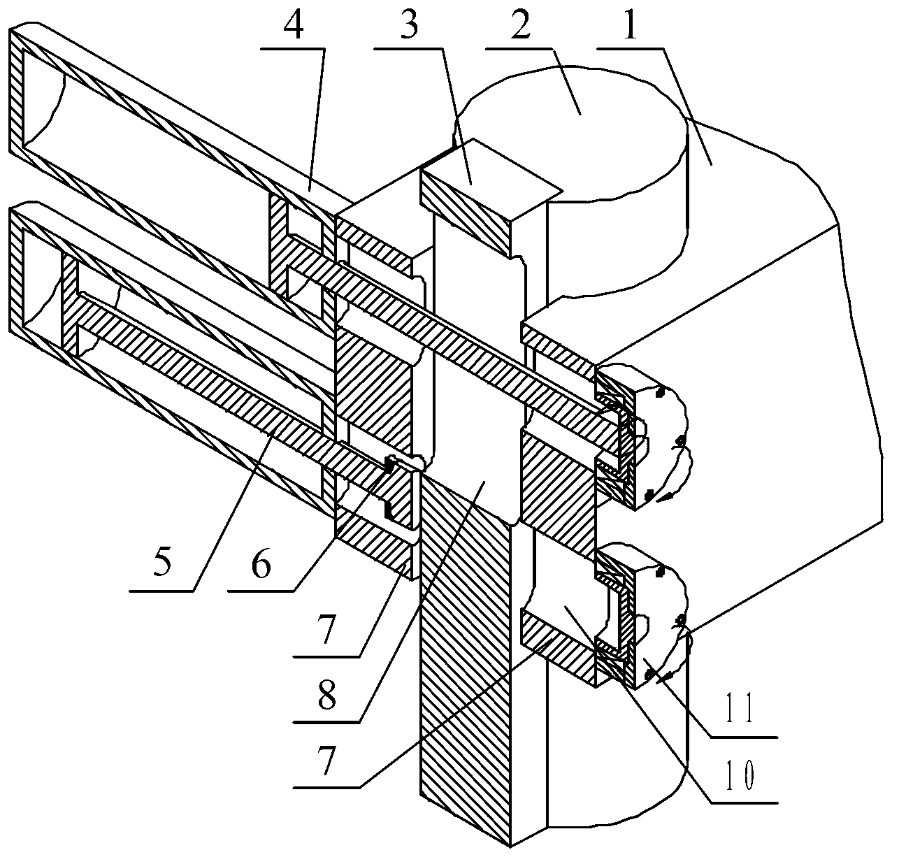
[0040] See attached Figure 4 , attached Figure 5 And attached Image 6The difference between this implementation and Embodiment 1 is that two hydraulic cylinder clamping mechanisms 4 form a group, and the outer sides of the two elastic clamping flaps 7 are symmetrically provided with the hydraulic cylinder clamping mechanism 4, and the hydraulic cylinder The end of the piston rod 5 in the clamping mechanism 4 is a flattened disc, and the two sides of the rectangular section member 3 are symmetrically opened with T-shaped grooves in the vertical direction. 5. The flattened discs at the ends are matched with the T-shaped grooves on both sides to realize relative sliding. The hydraulic oil cylinders on both sides of the clamping mechanism 4 are filled with hydraulic oil in the rod cavity at the same time. The symmetrical hydraulic cylinder clamps on both sides The piston rod 5 in the clamping mechanism 4 moves away from the elastic clamping valve 7 at the same time to realize...
PUM
 Abstract
Description
Claims
Application Information
 - R&D
- Intellectual Property
- Life Sciences
- Materials
- Tech Scout
- Unparalleled Data Quality
- Higher Quality Content
- 60% Fewer Hallucinations
Browse by: Latest US Patents, China's latest patents, Technical Efficacy Thesaurus, Application Domain, Technology Topic, Popular Technical Reports.
© 2025 PatSnap. All rights reserved.Legal|Privacy policy|Modern Slavery Act Transparency Statement|Sitemap|About US| Contact US: help@patsnap.com


