Pipeline depressurization device

A pressure-reducing device and pipeline technology, which is applied in the direction of pipe components, pipes/pipe joints/fittings, mechanical equipment, etc., can solve problems such as blockage of pressure-reducing components, complexity of pressure-reducing components, and high equipment costs, and achieve easy maintenance and operation. Simple structure, intensified friction and collision effect

Inactive Publication Date: 2013-08-21
重庆恒伟林汽车零部件有限公司
View PDF8 Cites 8 Cited by
  • Summary
  • Abstract
  • Description
  • Claims
  • Application Information

AI Technical Summary

Problems solved by technology

[0002] In the prior art, most of the internal decompression used in high-pressure pipelines are decompression valves or buffer tanks. The decompression effect is achieved by multi-stage shunting or increasing the flow cross-sectional area. The disadvantage is that the processing and manufacturing of decompression components is complicated. In addition, The installation is also more complicated, and the equipment cost is relatively high
The traditional pipeline depressurization device has a narrow application range. In order to avoid the depressurization element being blocked by small solid particles, it can only be applied to single-phase fluid depressurization without solid particles in the medium.

Method used


Image

  • Pipeline depressurization device
  • Pipeline depressurization device
  • Pipeline depressurization device

Examples


Embodiment Construction

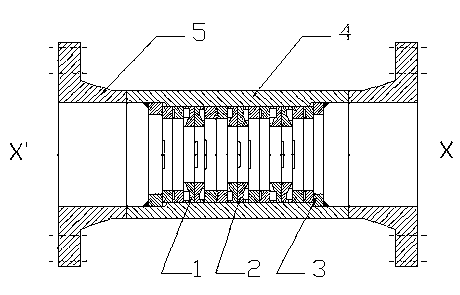
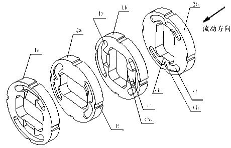
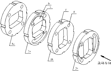
[0008] like figure 1 As shown, the pipeline depressurization device includes a main body of the pipeline depressurization device composed of a straight pipe section 4 and a neck flange 5, and a rectangular hole diversion plate 1 and a rectangular hole diverter plate 2 are superimposed to form a multi-stage depressurization group. , the positioning ring 3 is welded on the inner wall of the pipeline to fix the pressure reducing element. The rectangular hole guide plate 1 and the rectangular hole flow distribution plate 2 are formed into a rectangular hole pressure reduction group in pairs according to the principle of parallel rectangular flow channel walls. The walls are stacked vertically, with the XX' axis as the center line. Multiple pairs of rectangular hole pressure-reducing elements are stacked to form the multi-stage pressure-reducing group of this pipeline pressure-reducing device. The pressure-reducing group can be adjusted according to the medium pressure values ​​at ...


PUM


Abstract

The invention discloses a pipeline depressurization device which aims at achieving a depressurization purpose by improving a turbulence effect of media in a flow channel, intensifying flow friction and clash of the media in a flow process, and consuming the energy of the flow media. The device comprises a pipeline depressurization device main body consisting of a straight-tube section (4) and hubbed flanges (5), wherein rectangular hole guide disks (1) and rectangular hole shunt disks (2) are superposed to form multi-stage depressurization groups, and locating rings (3) for fixing depressurization components are mounted on an inner wall of a pipeline.

Description

technical field [0001] The invention relates to a pipeline decompression device with a disc-type decompression element. Background technique [0002] In the prior art, most of the internal decompression used in high-pressure pipelines are decompression valves or buffer tanks. The decompression effect is achieved by multi-stage shunting or increasing the flow cross-sectional area. The disadvantage is that the processing and manufacturing of decompression components is complicated. In addition, The installation is also complicated, and the equipment cost is relatively high. The traditional pipeline decompression device has a narrow application range. In order to avoid the decompression element being blocked by small solid particles, it can only be applied to single-phase fluid decompression without solid particles in the medium. Contents of the invention [0003] The purpose of the present invention is to increase the turbulence effect of the medium in the flow channel, int...

Claims


Application Information

Patent Timeline
Patent Type & Authority Applications(China)
IPC IPC(8): F16L55/027
Inventor 余龙俞树荣桂芳
Owner 重庆恒伟林汽车零部件有限公司
Why Eureka
Try Eureka