Air conditioning system for vehicle

A technology for air conditioning systems and vehicles, which is applied in vehicle components, air handling equipment, heating/cooling equipment, etc., and can solve problems such as high cost and system complexity.

Inactive Publication Date: 2013-08-21
CALSONIC KANSEI CORP
View PDF7 Cites 4 Cited by
  • Summary
  • Abstract
  • Description
  • Claims
  • Application Information

AI Technical Summary

Problems solved by technology

That is, in order to prevent the circulating flow of indoor air of an undesired temperature and achieve comfortable zone air conditioning, the heat exchangers 117 and 124 of the seat air conditioner 111 are required, which leads to complexity and high cost of the system.

Method used


Image

  • Air conditioning system for vehicle
  • Air conditioning system for vehicle
  • Air conditioning system for vehicle

Examples


no. 1 approach

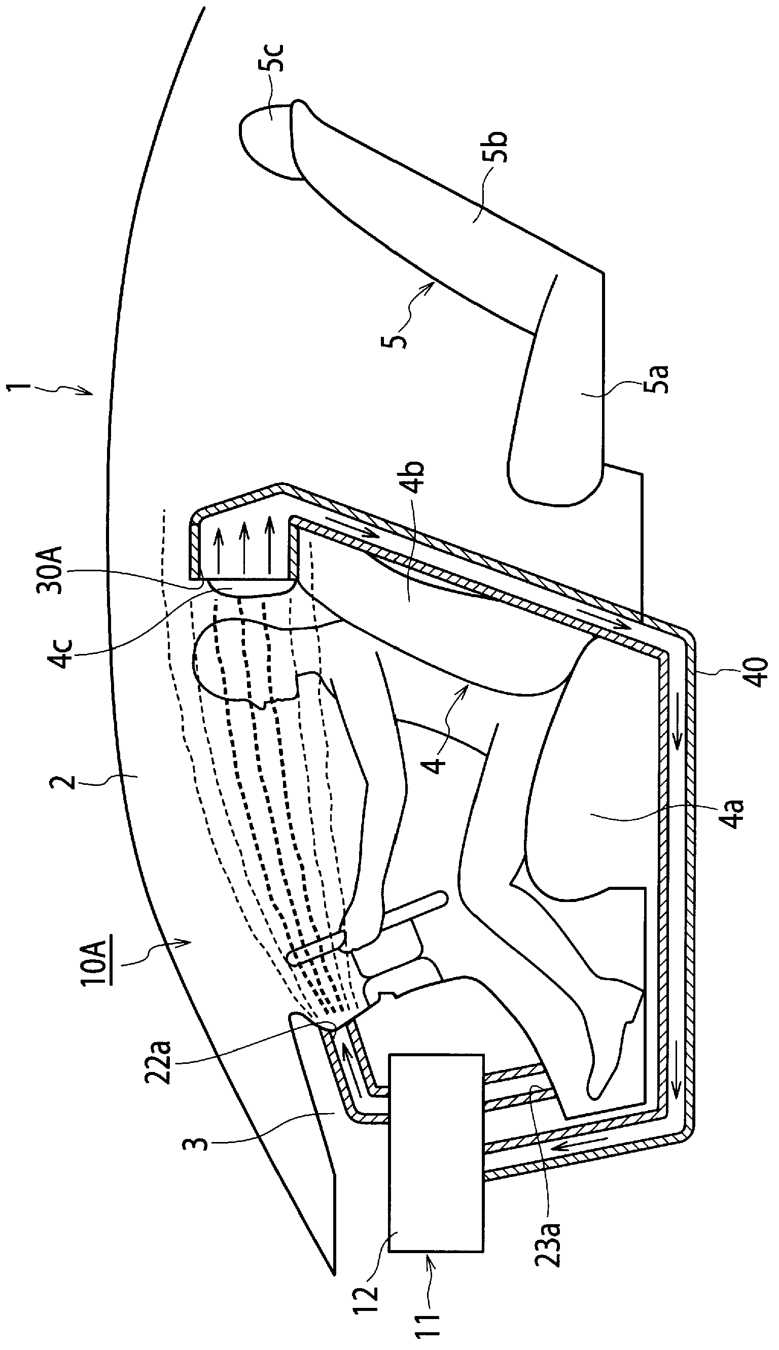
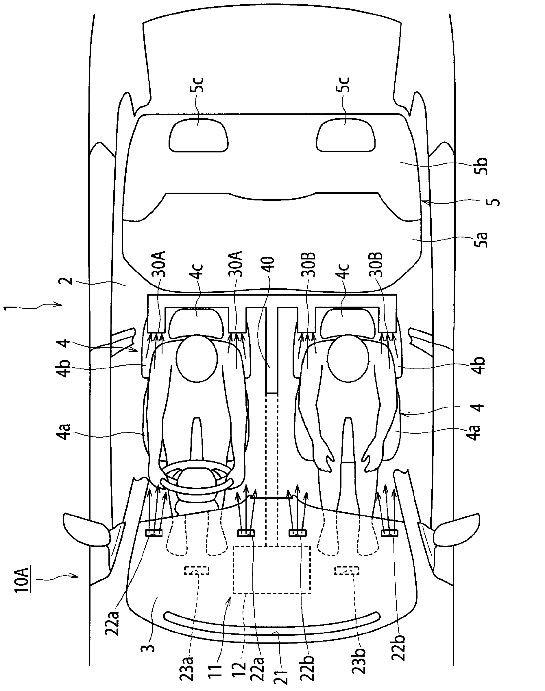
[0037] Figure 1 ~ Figure 3 10 A of air conditioning systems of 1st Embodiment are shown. Such as figure 1 and figure 2 As shown, the vehicle 1 has an instrument panel 3 at the forefront in the passenger compartment 2 . In the compartment 2, two front seats (driver's seat, passenger seat) 4 and a long rear seat 5 are arranged. Each front seat 4 has a seat cushion 4a, a backrest 4b, and a headrest 4c. The rear seat 5 has a seat cushion 5a, a backrest 5b and two headrests 5c.

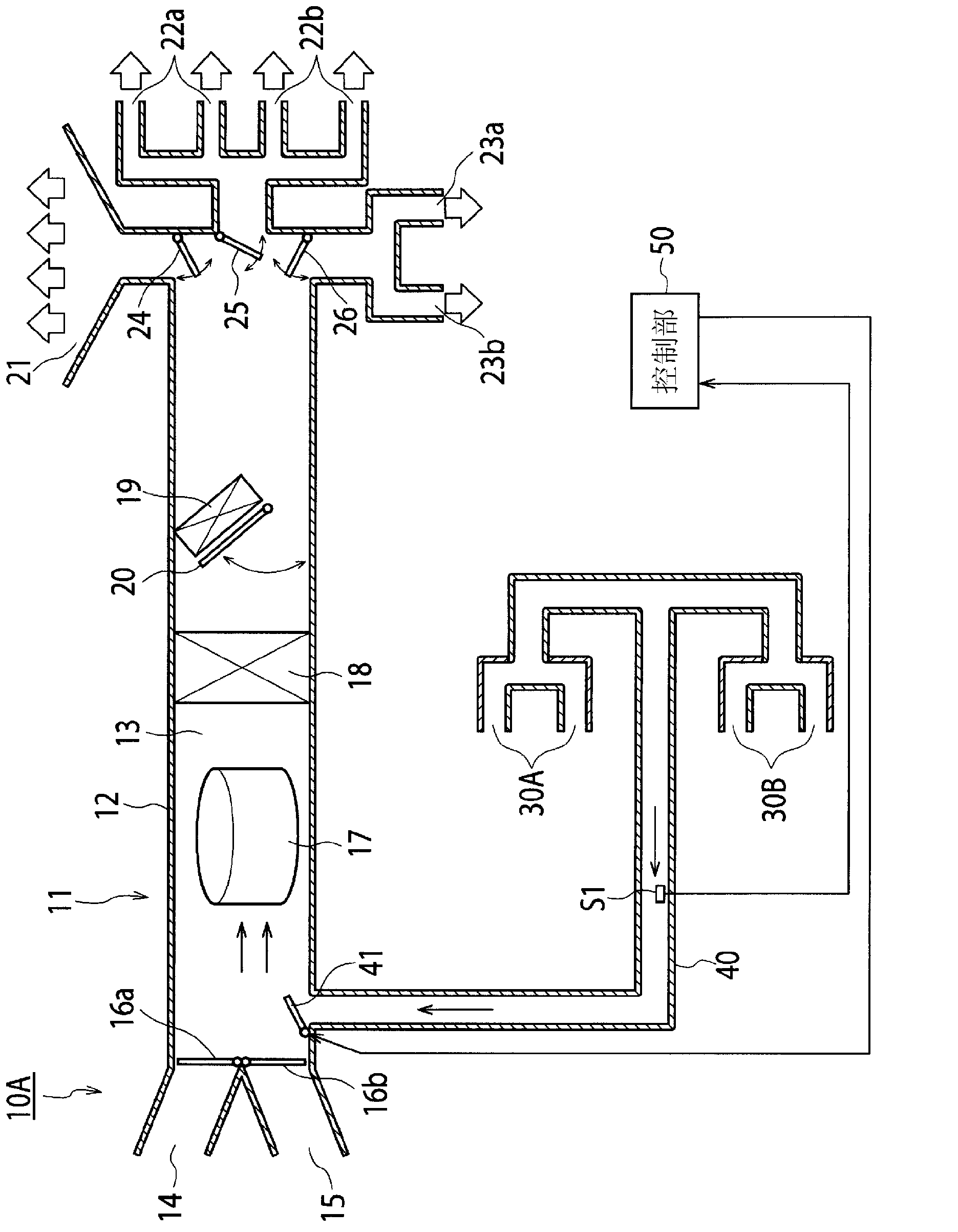
[0038] Such as Figure 1 ~ Figure 3 As shown, the air-conditioning system 10A includes an air-conditioning device 11, a suction port 30A and a suction port 30B respectively arranged around the front seat 4, and an auxiliary channel for connecting these suction ports 30A and 30B to the main duct 13 of the air-conditioning device 11. Channel 40. An air supply passage is formed inside the main duct 13 .

[0039] The air conditioner 11 has an air conditioner unit 12 arranged inside the instrument pa...

no. 2 approach

[0061] Figure 4 and Figure 5 An air conditioning system 10B according to a second embodiment of the present invention is shown. Such as Figure 4 and Figure 5 As shown, in the air conditioning system 10B, the connection position of the other end of the sub duct 40 is different from that of the air conditioning system 10A of the first embodiment described above. The other end of the secondary channel 40 is connected to a part of the main channel 13 between the fan 17 and the evaporator 18 . Also, a sub blower 42 for sucking air from the suction port 30A and the suction port 30B is provided in the sub duct 40 . The auxiliary fan 42 is controlled by the control unit 50 .

[0062] The same reference numerals are assigned to other configurations that are the same as or equivalent to those of the first embodiment, and repeated descriptions are omitted.

[0063] The operation of the air conditioning system 10B described above will be described. When the air conditioner 11 i...

no. 3 approach

[0070] Figure 6 and Figure 7 10 C of air conditioning systems of 3rd Embodiment are shown. Such as Figure 6 and Figure 7 As shown, the air conditioning system 10C includes, in addition to the system structure of the first embodiment, a suction port 30C and a suction port 30D disposed around the rear seat 5, and a connection between the suction port 30C and the suction port 30D. In the main channel 13 of the air conditioner 11 (refer to image 3 ) of the secondary channel 43.

[0071] The same reference numerals are assigned to other configurations that are the same as or equivalent to those of the first embodiment, and repeated descriptions are omitted.

[0072] The air inlet 30C of the right rear seat 5 (or the air outlet 30D of the left rear seat 5 ) is provided on both sides of the headrest 5 c above the backrest 5 b. A total of four suction ports 30C and 30D are opened directly behind the upper body of the passenger in the rear seat 5 .

[0073] The other end of...


PUM


Abstract

An air conditioning system for a vehicle is provided with: an air conditioning device having a main air blower, a main duct, and a heat exchange section, the air conditioning device converting air, which is sucked into the main duct by the main air blower, into air conditioning air by the heat exchange section and blowing the air conditioning air into the vehicle interior; a suction opening disposed in the vicinity of an occupant's seat; and a sub-duct having one end connected to the suction opening and sucking air from the suction opening. The air conditioning device sucks the air, which is sucked into the sub-duct, into the main duct and blows the air again into the vehicle interior. In the air conditioning system, the air conditioning air blown into the vehicle interior by the air conditioning device is sucked from the suction opening disposed in the vicinity of the occupant's seat. This causes the air conditioning air to be collected and at the same time the air conditioning air flowing rearward beyond the suction opening to be reduced, and as a result, comfortable zone air conditioning can be performed. In a zone air conditioning mode, air conditioning air having a desired temperature is generated by the heat exchange section. This means that the installation of a heat exchange section exclusive for the zone air conditioning is not essential, and as a result, the system can be simplified and the cost can be reduced.

Description

technical field [0001] The present invention relates to an air-conditioning system for a vehicle [an air-condition system for a vehicle] capable of performing zoned air-conditioning (personal air-conditioning) using a part of the vehicle cabin (for example, around passengers) as an air-conditioned area. Background technique [0002] As an air-conditioning system for a vehicle, a zoned air-conditioning system has been proposed that does not air-condition the entire vehicle compartment, but air-conditions only the surroundings of passengers. Patent Document 1 below discloses a conventional zoned air conditioning system. Such as Figure 15 As shown, the vehicle air conditioning system 100 disclosed in Patent Document 1 includes a suction port 102 opened on the upper surface of the seat cushion 101a of the seat 101, and a suction port opened above the headrest 101c of the seat 101. The air outlet [blow-out port] 103, and the channel 104 that connects the suction port 102 and th...

Claims


Application Information

Patent Timeline
Patent Type & Authority Applications(China)
IPC IPC(8): B60H1/00B60H1/34
CPCB60H1/247B60H2001/002B60H1/242B60H1/3407
Inventor 矢岛敏雄藤田隆司
Owner CALSONIC KANSEI CORP
Why Eureka
Try Eureka