High-pressure pump

A technology for high-pressure pumps and pump components, which is applied in the direction of pumps, multi-cylinder pumps, fuel injection pumps, etc., can solve problems such as pump damage, and achieve the effects of improving lubrication, reducing friction, and improving hydraulic lubrication

Inactive Publication Date: 2013-08-21
ROBERT BOSCH GMBH
View PDF5 Cites 5 Cited by
  • Summary
  • Abstract
  • Description
  • Claims
  • Application Information

AI Technical Summary

Problems solved by technology

Particles can also be generated here by abrasio

Method used


Image

  • High-pressure pump
  • High-pressure pump
  • High-pressure pump

Examples


Embodiment Construction

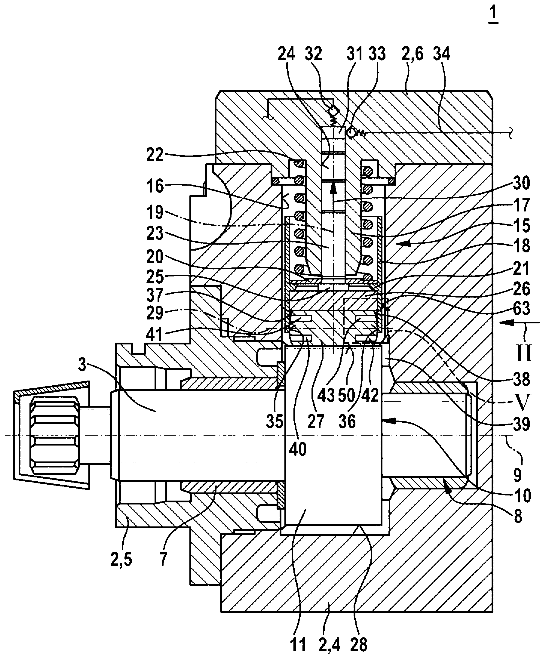
[0017] figure 1 The high-pressure pump 1 corresponding to the first exemplary embodiment of the invention is shown in a schematic axial section. The high-pressure pump 1 can in particular be designed as a radial or in-line piston pump. Specifically, the high-pressure pump 1 is suitable for use as a fuel pump for a fuel injection system of an air-compressed self-ignition internal combustion engine. A preferred use of the high-pressure pump 1 is a fuel injection system with a fuel distributor platen, where high-pressure diesel fuel is stored. However, the high-pressure pump 1 according to the invention is also suitable for other applications.

[0018] The high-pressure pump 1 has a multi-part pump housing 2 and a drive shaft 3 arranged in the pump housing 2 . In this exemplary embodiment, the pump housing 2 comprises a base body 4 , a flange 5 connected to the base body and a cylinder head 6 . The drive shaft 3 is mounted on a bearing 7 on one side on the flange 5 and on a b...


PUM


Abstract

A high-pressure pump (1) which serves in particular as a radial piston pump or in-line piston pump for fuel injection systems of air-compressing, auto-ignition internal combustion engines comprises a pump assembly (15) and a drive shaft (3) which has a cam (10) assigned to the pump assembly (15). The pump assembly (15) comprises a roller (27), which runs on a running surface (11) of the cam (10), and a tappet body (18) on which the roller (27) is axially mounted. Lubricant recesses (40 to 49, 60 to 62) are formed on at least one side surface (37, 38) of the roller (27) and/or on at least one run-on surface (35, 36) of the tappet body (18) on which the roller is axially mounted by means of the side surface (37, 38) thereof. Advantageous lubrication is hereby possible for wear reduction.

Description

technical field [0001] The invention relates to a high-pressure pump, especially a radial piston pump or an in-line piston pump. In particular, the invention relates to the field of fuel pumps for fuel injection systems of air-compressed self-ignition internal combustion engines. Background technique [0002] A high-pressure pump for a fuel injection system of an internal combustion engine is known from DE 10 2005 046 670 A1. The known high-pressure pump comprises a pump housing in which a pump element is arranged, the pump element comprising a pump piston driven in a stroke movement by a drive shaft. The pump piston is guided displaceably in a cylinder bore of a part of the pump housing and delimits a pump working space in the cylinder bore. The pump piston is supported on the drive shaft via a hollow cylindrical tappet, wherein the tappet is guided displaceably in a bore in a part of the pump housing in the direction of the longitudinal axis of the pump piston. In the t...

Claims


Application Information

Patent Timeline
IPC IPC(8): F02M59/10
CPCF02M59/102F02M63/0001F04B1/0408F04B1/0417F04B1/0426
Inventor F·卢卡雷利F·肖尔茨
Owner ROBERT BOSCH GMBH
Why Eureka
Try Eureka