Release bearing cage

A technology of bearing cage and separation bearing, applied in the direction of bearing, roller bearing, bearing assembly, etc., can solve the problems of bearing failure, uneven circular outer contour, unbalanced operation of bearing cage, etc., to achieve long service life, The effect of imbalance minimization

Active Publication Date: 2021-07-30
AB SKF
View PDF7 Cites 0 Cited by
  • Summary
  • Abstract
  • Description
  • Claims
  • Application Information

AI Technical Summary

Problems solved by technology

However, these bearing cages are disadvantageous because they have a non-uniform circular outer contour when assembled, which leads to an unbalance of the bearing cage during operation
In addition, non-uniformly distributed forces thus act on the bearing cage, which can lead to failure of the bearing cage and thus a complete failure of the bearing

Method used


Image

  • Release bearing cage
  • Release bearing cage

Examples


Embodiment Construction

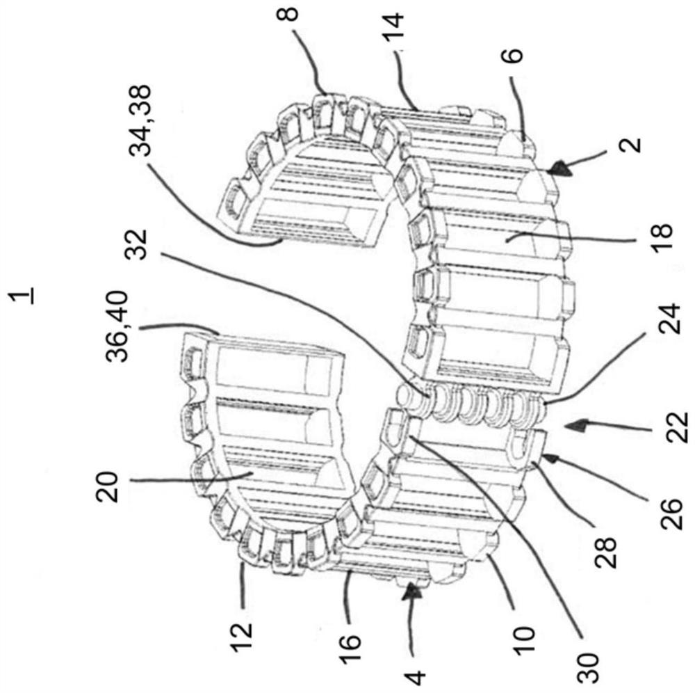
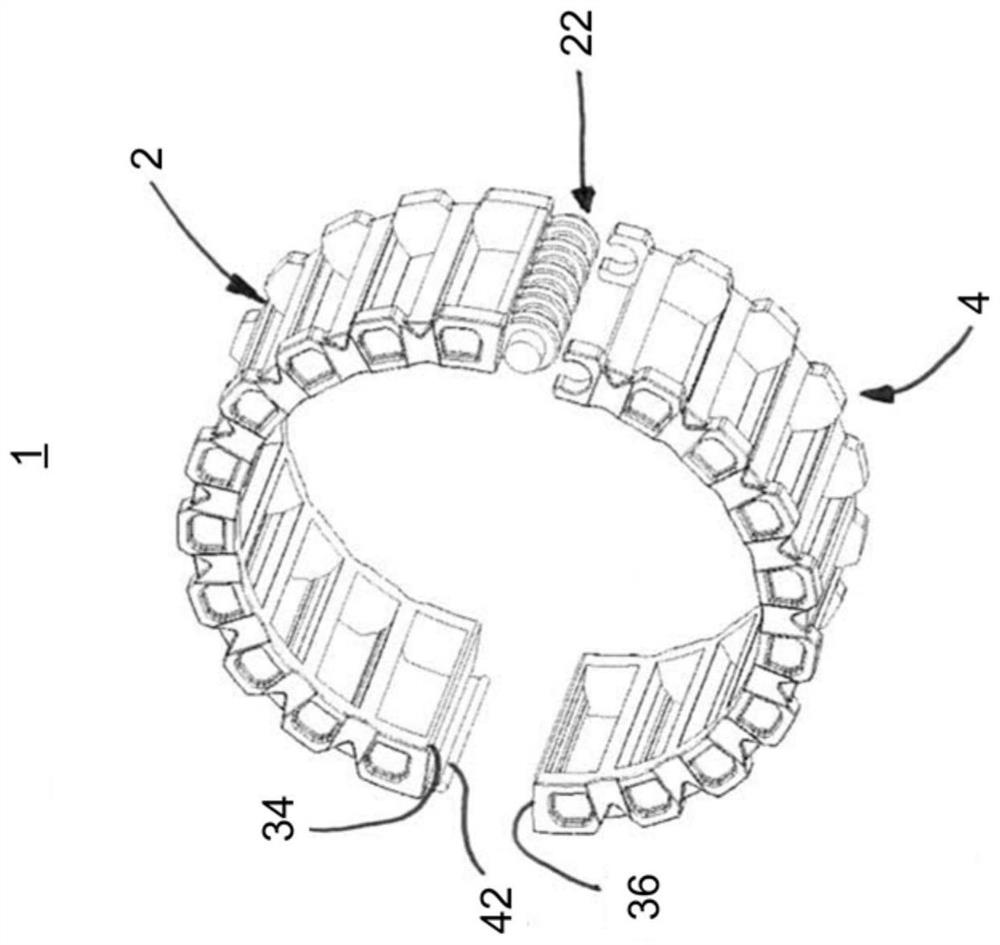
[0024] figure 1 and figure 2 A schematic perspective view of a release bearing cage 1 of a rolling element bearing assembly (not shown) comprising a first and a second bearing cage segment 2 , 4 is shown, respectively. here in figure 2 , an alternative design of the proposed release bearing cage 1 is shown. Furthermore, each bearing cage segment 2, 4 comprises two side ring portions 6, 8, 10, 12, each axially spaced from each other via a bridge 14, 16, with a rolling element receiving recess formed therebetween 18, 20. The rolling element receiving pockets 18, 20 are configured to receive rolling elements (not shown) of a rolling element bearing assembly to keep them spaced from each other and to guide them.

[0025] In order to improve the handling behavior of the split bearing cage 1 , in particular for use with a one-piece crankshaft, the two bearing cage segments 2 , 4 are connected to each other via a swivel joint arrangement 22 .

[0026] like figure 1 and 2 As ...


PUM


Abstract

A split bearing cage (1) for a rolling element bearing assembly is disclosed, comprising at least one first and one second bearing cage segment (2; 4), wherein each bearing cage segment (2; 4 ) comprises two side ring portions (6; 8; 10; 12), each axially spaced from each other by a bridge (14; 16), between which a rolling element receiving recess (18; 20) is formed, said The rolling element receiving pockets are configured to receive and guide rolling elements of a rolling element bearing assembly spaced apart from each other, wherein at least two bearing cage segments (2; 4) are connected to each other via a swivel joint arrangement (22).

Description

technical field [0001] The invention relates to a release bearing cage. Background technique [0002] Bearing cages for rolling element bearings generally comprise two side rings axially spaced from each other by a bridge. The bridges here are arranged continuously in the circumferential direction of the bearing cage and form recesses for receiving rolling elements. Due to its arrangement in the recesses, such a bearing cage holds the rolling elements at a distance in order to enable a better rolling behavior. [0003] During operation, bearing cages are subjected to considerable mechanical stress by friction, shear and tension, so they are usually constructed in one piece and are made, for example, of sheet steel. [0004] However, the use of a one-piece bearing cage is not possible if axial mounting of the bearing cage to the bearing location is not possible, such as with a one-piece crankshaft which is typically configured as an angled roller support. [0005] Split be...

Claims


Application Information

Patent Timeline
Patent Type & Authority Patents(China)
IPC IPC(8): F16C33/46F16C33/50
CPCF16C33/4617F16C33/504F16C9/00F16C19/26F16C33/4635F16C2226/74F16C2226/62F16C33/516F16C2208/02F16C33/3862F16C33/3875F16C33/3887F16C2208/00F16C2220/04F16C2300/02
Inventor F.迈耶J.韦格莱因
Owner AB SKF
Why Eureka
Try Eureka