Trailer tailstock rotation mechanism

A technology of rotating mechanism and tailstock, which is applied in the direction of motor vehicles, substructures, vehicle parts, etc. It can solve the problems that cannot be turned upside down and can not be satisfied at the same time, and achieve the effect of smooth turning

Active Publication Date: 2015-09-16
LINGBAYI ELECTRONICS GRP SICHUAN HONGLUN MACHINERY
View PDF7 Cites 0 Cited by
  • Summary
  • Abstract
  • Description
  • Claims
  • Application Information

AI Technical Summary

Problems solved by technology

[0006] When the existing trailer technology is used for road transportation and rail transportation, the tailstock and vehicle frame with suspension cannot be turned up, and the position of the trailer in the height direction cannot be changed in the way of turning up. When large-scale equipment When transporting, it is impossible to meet the requirements of the road transport limit and the railway transport limit at the same time

Method used


Image

  • Trailer tailstock rotation mechanism
  • Trailer tailstock rotation mechanism
  • Trailer tailstock rotation mechanism

Examples


Embodiment 1

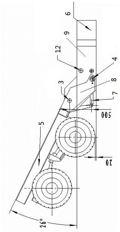
[0039] As a preferred embodiment of the present invention, it includes a chassis tailstock 5 and a chassis seating frame 6. The chassis tailstock 5 is fixedly installed with a turning support 8, and the chassis tailstock 5 is hinged to the chassis seating frame 6 through the turning support 8 , The chassis tailstock 5 rotates around the hinge center to make the chassis tailstock 5 flip up and down, refer to the instructions attached figure 1 , That is, a schematic diagram of the structure of the present invention after being turned over is given. When the chassis tailstock 5 is turned upwards, the height between the chassis seat frame 6 and the ground can be reduced, thereby making the large-sized chassis carried on the chassis seat frame 6 The device 15 is also lowered in height.

Embodiment 2

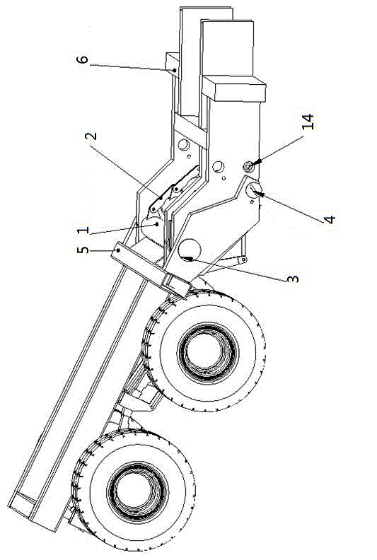
[0041] As another preferred embodiment of the present invention, a turning support shaft 3 is provided on the turning support 8, a support seat 9 is fixedly installed on the chassis frame 6 and the turning support shaft 3 penetrates the turning support 8 and the support seat 9. The chassis tailstock 5 is hinged with the chassis seat frame 6 through the turning support shaft 3. When the cargo is loaded on the chassis seat frame 6, the chassis tailstock 5 turns upwards. At this time, the turning support 8 also turns over and supports The seat 9 does not turn over, and the support seat 9 gradually moves downward along with the chassis seat frame 6. Such a structure makes the overturning of the chassis tailstock 5 smoother, and the rest is the same as the first embodiment.

Embodiment 3

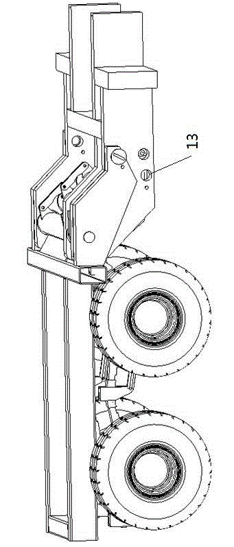
[0043] Refer to the instructions attached image 3 As another preferred embodiment of the present invention, a spring torsion accumulator 1 is installed between the supporting seats 9. The spring torsion accumulator 1 includes a pin shaft, a torsion spring 10 sleeved on the pin shaft, and a torsion spring 10 sleeved on the pin shaft. For the outer tube 11 outside the spring 10, both ends of the pin shaft are fixed on the support base 9, one end of the torsion spring 10 is fixed on the pin shaft, and the other end of the torsion spring 10 is fixed on the outer tube 11, under the action of the torsion spring 10 The outer tube 11 is driven to rotate, and the outer tube 11 is connected with the chassis tailstock. There are three spring torsion accumulators 1, and the outer tubes 11 of every two spring torsion accumulators 1 are connected and driven by a link mechanism 2. The turning support 8 and the support base 9 are respectively provided with a marching state locking pin hole 12...


PUM


Abstract

The invention discloses a rotating mechanism of a trailer tail frame, and relates to the technical field of structures of trailer tail frames. The rotating mechanism of the trailer tail frame comprises a chassis tail frame and a chassis base framework, wherein an overturning support is fixedly arranged on the chassis tail frame, the chassis tail frame is hinged to the chassis base framework through the overturning support, and the chassis tail frame rotates around a hinged center so that the chassis tail frame can overturn upwards and downwards. By means of the rotating mechanism of the trailer tail frame, a trailer can be adjusted in the height direction in road transportation and railway transportation, and meanwhile the requirement for limits of the road transportation and the railway transportation can be met.

Description

Technical field [0001] The invention relates to the technical field of trailer tail frame structures, and specifically to a trailer tail frame rotating mechanism that can simultaneously meet the requirements of road and railway transportation. Background technique [0002] The trailer whose total weight is borne by itself is called a full trailer, and usually a full trailer is also referred to as a trailer. Features: A vehicle that has no power, independent load, and relies on other vehicles to drive. A trailer is an unpowered road vehicle that needs to be towed by a car due to its design and technical characteristics to be used normally. It is used to carry people or goods. A semi-trailer is a trailer whose axle is placed behind the center of gravity of the vehicle (when the vehicle is evenly loaded) and is equipped with a coupling device that can transmit horizontal or vertical forces to the tractor. That is, part of the total weight of the trailer is borne by the tractor...

Claims


Application Information

Patent Timeline
Patent Type & Authority Patents(China)
IPC IPC(8): B62D63/06B62D21/18
Inventor 谭建国陈旭王军张伟徐志林马思贵杨加春朱家洪余武林詹爱民
Owner LINGBAYI ELECTRONICS GRP SICHUAN HONGLUN MACHINERY
Why Eureka
Try Eureka