
Electromagnetic power take-off system of garbage dump micro truck and power take-off method thereof

A garbage truck and electromagnetic technology, which is applied in the direction of garbage receptacle, transportation and packaging, etc., can solve the problems of high power, inflexible installation position of the micro-card chassis, and no power take-off window for the micro-card chassis gearbox.

Active Publication Date: 2013-08-28
CNHTC CHENGDU WANGPAI COMML VEHICLE
View PDF6 Cites 2 Cited by
  • Summary
  • Abstract
  • Description
  • Claims
  • Application Information

AI Technical Summary

Problems solved by technology

Due to the complex layout of the micro-card chassis and the limitation of the placement of batteries and motors, the power unit must be small in size and high in power, and the requirements for the power unit (mainly including the motor inside) and the gear pump are relatively high. resulting in generally higher prices
Moreover, the motor, gear pump, hydraulic valve, control panel, etc. in the power unit are generally integrated together, so the power unit has a large volume, and the installation position on the micro-card chassis is limited and not flexible enough
[0003] The existing micro-card chassis gearbox has no power take-off window, and the existing micro-card dump garbage truck does not use any power-take-off method, and cannot obtain driving force from other power equipment itself, which makes the micro-card dump garbage truck Power components such as batteries and motors have to be added to power its hydraulic system, which increases the complexity of the micro-card chassis layout

Method used


Image

  • Electromagnetic power take-off system of garbage dump micro truck and power take-off method thereof
  • Electromagnetic power take-off system of garbage dump micro truck and power take-off method thereof

Examples


Embodiment

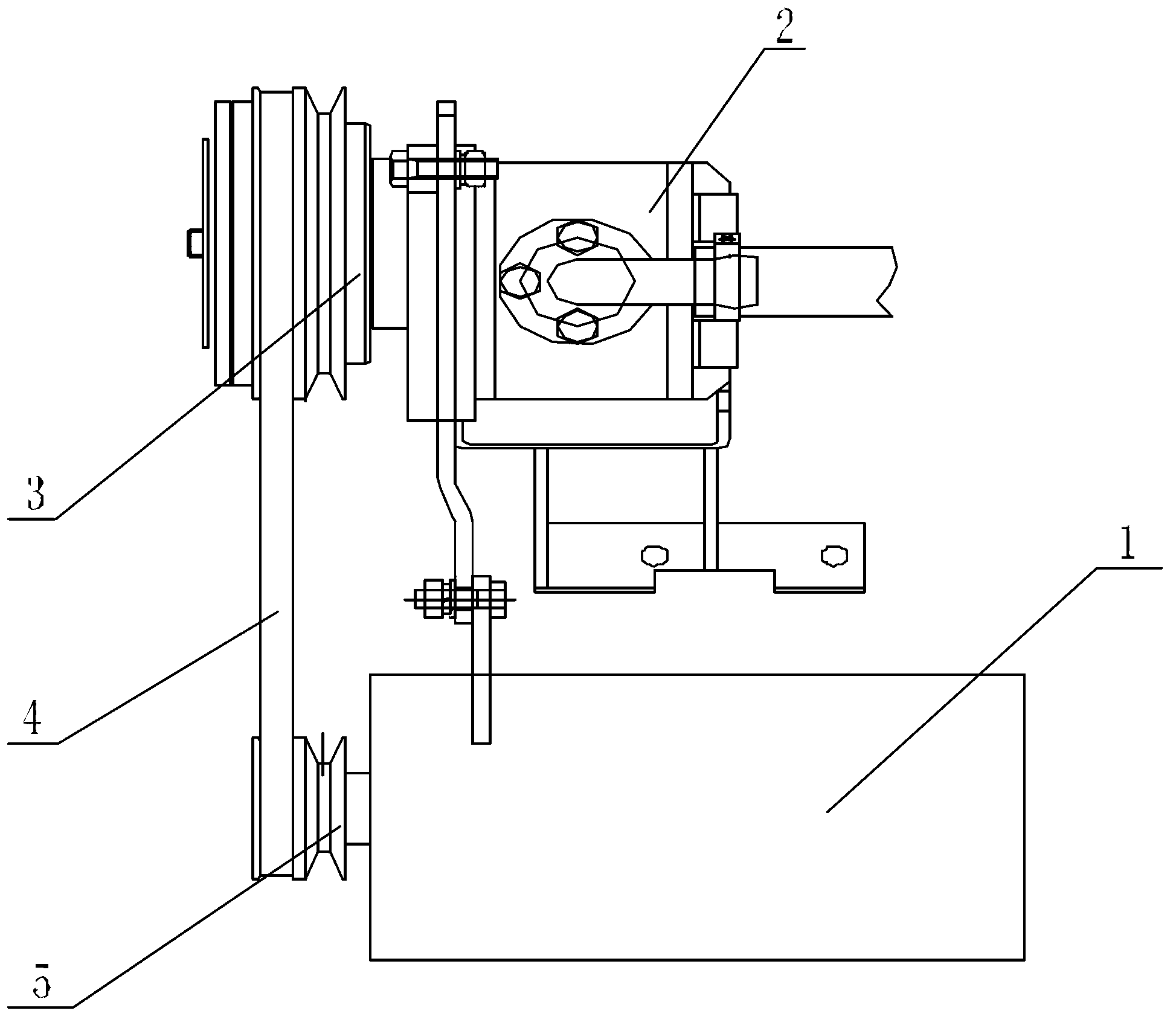
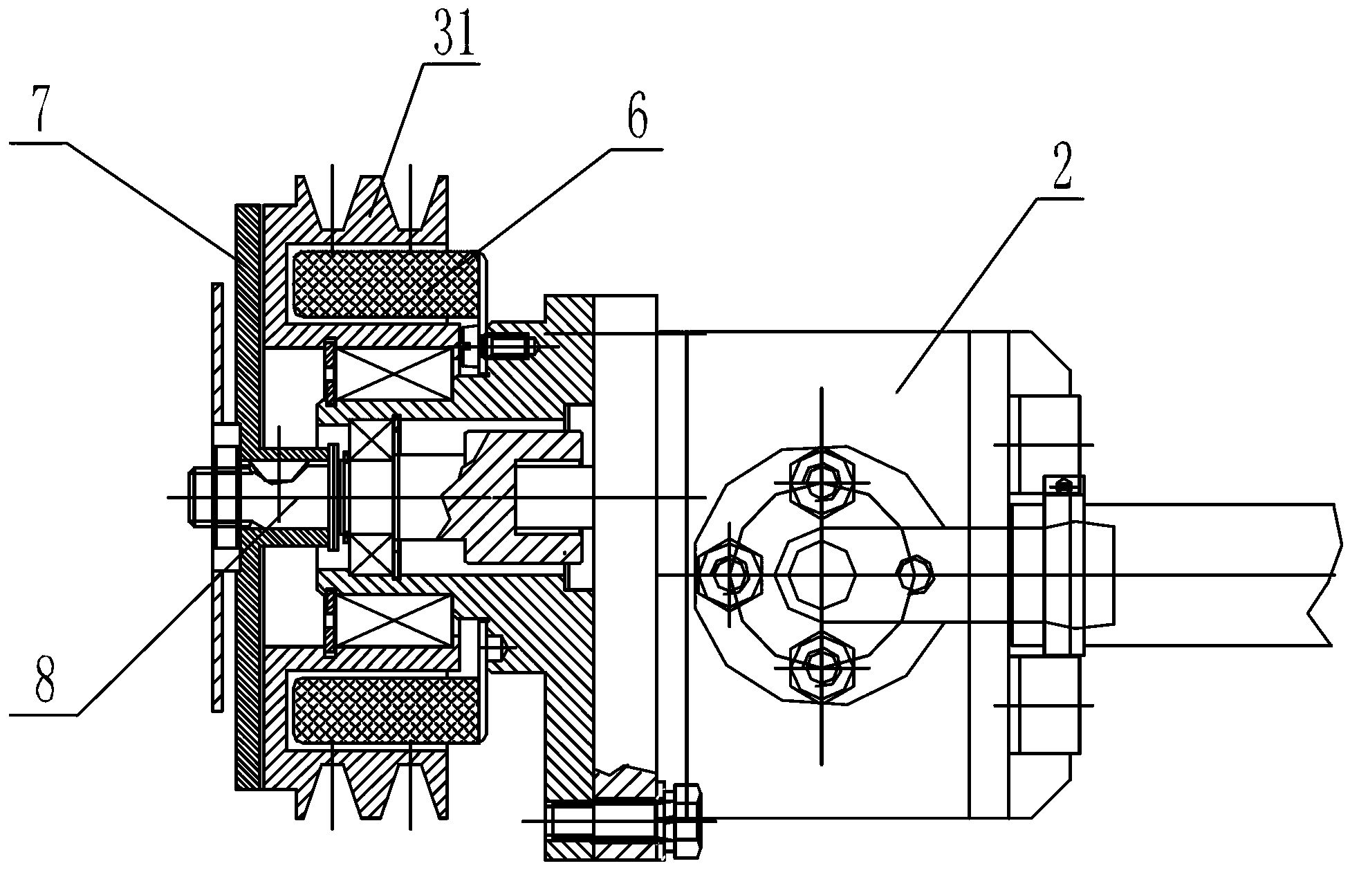
[0022] like Figure 1 ~ Figure 2 As shown, an electromagnetic power take-off system of a micro-card dump truck includes an engine 1 and an electromagnetic clutch 3, the engine 1 is provided with an engine power output wheel 5, the electromagnetic clutch 3 is provided with an electromagnetic clutch power input wheel 31, and the electromagnetic clutch The power input wheel 31 is dynamically connected with the engine power output wheel 5 . Engine 1 outputs power by engine power output wheel 5, and this power output is on the electromagnetic clutch power input wheel 31 of electromagnetic clutch 3, drives the electromagnetic clutch power input wheel 31 of electromagnetic clutch 3 to rotate, makes and electromagnetic clutch power input wheel 31 Other equipment or devices connected to the power are in normal operation.

[0023] like figure 2 As shown, the inner center shaft of the electromagnetic clutch 3 is provided with a bearing sleeve, and an intermediate shaft 8 is installed ...


PUM


Abstract

The invention discloses an electromagnetic power take-off system of a garbage dump micro truck. The electromagnetic power take-off system of the garbage dump micro truck comprises an engine and an electromagnetic clutch, wherein an electromagnetic clutch power input wheel which is arranged on the electromagnetic clutch is connected with an engine power output wheel which is arranged on the engine in a power matching mode; a bearing sleeve is arranged on a center shaft which is arranged inside the electromagnetic clutch in a penetrating mode; an intermediate shaft is arranged inside the bearing sleeve in a communicated mode; an electromagnetic absorption plate is fixedly arranged at one end of the intermediate shaft; the electromagnetic absorption plate and the electromagnetic clutch power input wheel are arranged side by side in a parallel mode; the other end of the intermediate shaft is provided with a power output mechanism; an electromagnetic coil is arranged inside the electromagnetic clutch; and the positions of the electromagnetic coil and the electromagnetic absorption plate are mutually matched. According to the electromagnetic power take-off system of the garbage dump micro truck, an electromagnetic principle absorption assembly is added to the garbage dump micro truck and a clutch power take-off way is utilized to obtain power on the engine to achieve rotation of a gear pump in comparison with a direct power supply way of the traditional garbage dump micro truck, so that required power for a hydraulic system of the garbage dump micro truck is provided.

Description

technical field [0001] The invention relates to the technical field of micro-card dump truck power technology, in particular to an electromagnetic power take-off system and a power take-off method of a micro-card dump garbage truck. Background technique [0002] At present, the micro-card dump garbage trucks on the market generally use an additional power unit to provide power to the hydraulic system. Generally, a battery is installed on the micro-card chassis to supply power to the motor. Provide power. Due to the complex layout of the micro-card chassis and the limitation of the placement of batteries and motors, the power unit must be small in size and high in power, and the requirements for the power unit (mainly including the motor inside) and the gear pump are relatively high. This results in generally higher prices. Moreover, the motor, gear pump, hydraulic valve, control panel, etc. in the power unit are generally integrated together, so the power unit has a large ...

Claims


Application Information

Patent Timeline
Patent Type & Authority Applications(China)
IPC IPC(8): B65F3/24
Inventor 吴涛卢宗利
Owner CNHTC CHENGDU WANGPAI COMML VEHICLE
Learn More