A piezoelectric generating type damping adjustable oil-pneumatic suspension for engineering machinery or agricultural machinery

A technology for agricultural machinery and piezoelectric power generation, applied in mechanical equipment, springs, shock absorbers, etc., can solve problems such as high air compressibility, low energy conversion rate, and insignificant damping effect of air spring on vehicle vibration

Inactive Publication Date: 2016-01-27
HENAN POLYTECHNIC UNIV
View PDF13 Cites 0 Cited by
  • Summary
  • Abstract
  • Description
  • Claims
  • Application Information

AI Technical Summary

Problems solved by technology

The current relevant literature involves: Chinese patent ZL200810198710.4 realizes power generation by directly installing a power generation device between the vehicle frame and drive axle; Chinese patent ZL201010109914.3 uses hydraulic oil flow generated by vehicle vibration to drive hydraulic motors and generators to generate electricity. Chinese patent ZL200910063679.8 uses a power generation device installed on the telescopic end of the vehicle shock absorber spring to generate electricity. These technologies require the installation of more complicated power generation devices, which use the flow energy of the liquid to convert into electrical energy, and the energy conversion rate is low; Chinese patent ZL201110121853.7 The energy conversion is realized by using the piezoelectric generating air spring, but due to the high compressibility of the air, the pressure change of the air spring is small during the driving process of the vehicle, so the generated current is small, and the damping effect of the air spring on the vibration of the vehicle is not good. obvious

Method used


Image

  • A piezoelectric generating type damping adjustable oil-pneumatic suspension for engineering machinery or agricultural machinery

Examples


Embodiment Construction

[0014] In order to illustrate the present invention better, in conjunction with accompanying drawing, give examples as follows:

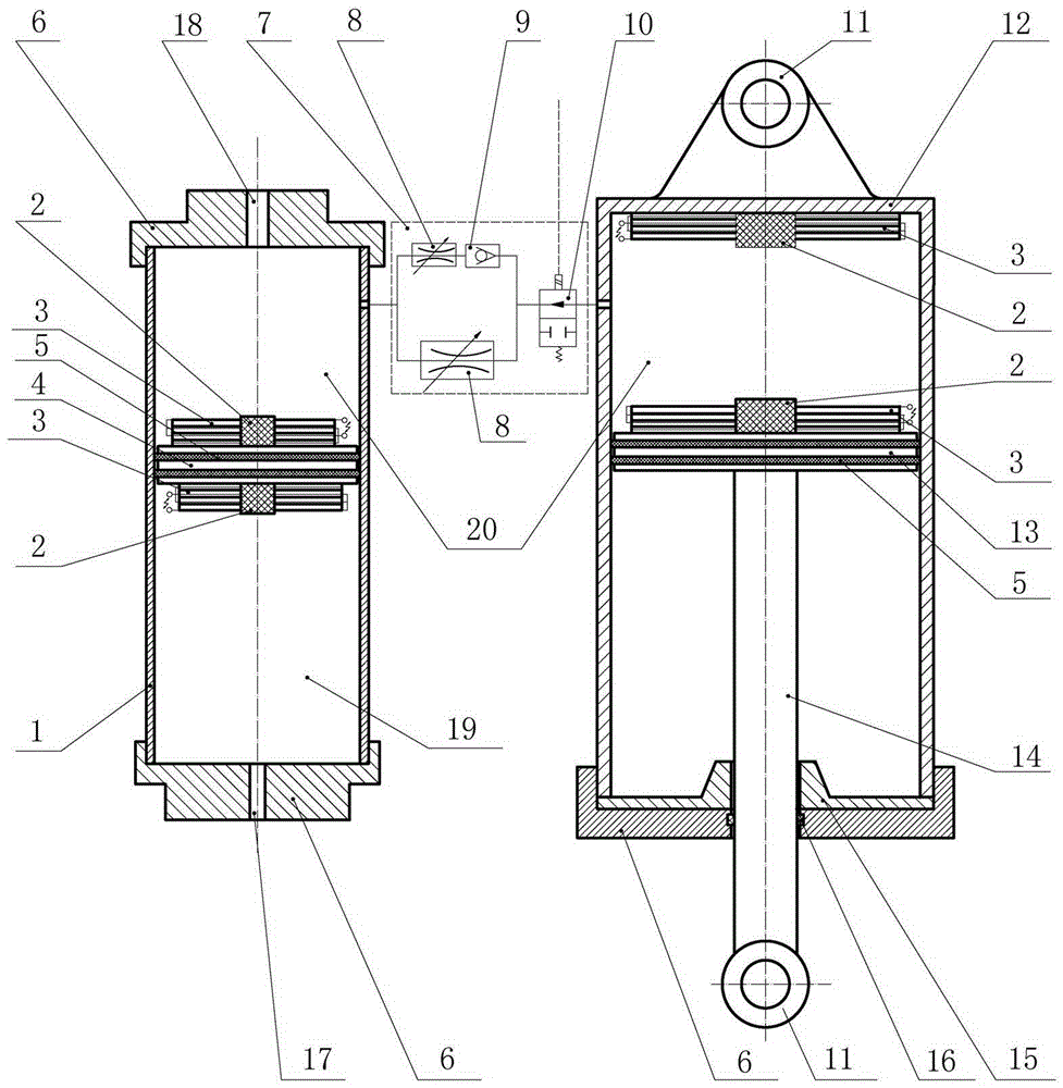
[0015] The piezoelectric generating type damping adjustable oil-pneumatic suspension of the present invention is composed of a suspension cylinder 12 and its components, an accumulator 1 and its components, and is characterized in that: a hydraulic valve group is passed between the suspension cylinder 12 and the accumulator 1 7 connection; the hydraulic valve group 7 is composed of an electromagnetic switch valve 10, an adjustable flow valve 8, and a one-way valve 9, wherein the adjustable flow valve 8 is connected with the one-way valve 9, and then connected in parallel with another adjustable flow valve 8, After parallel connection, the electromagnetic switch valve 10 is connected, and the electromagnetic switch valve 10 is connected with the remote control switch near the steering wheel to realize the locking function of the oil-gas suspension; by...


PUM


Abstract

The invention discloses a piezoelectric power generation type damping-adjustable hydro-pneumatic suspension, belongs to an oil-gas separation type hydro-pneumatic suspension and belongs to the field of automobile devices. The piezoelectric power generation type damping-adjustable hydro-pneumatic suspension is composed of a suspension cylinder (12), subassemblies of the suspension cylinder, an energy accumulator (1) and subassemblies of the energy accumulator and is characterized in that the suspension cylinder (12) and the energy accumulator (1) are connected through a hydraulic valve group (7), the hydraulic valve group (7) is composed of an electromagnetic switching valve (10), throttling valves (8) and a one-way valve (9), one of the throttling valves (8) is connected with the one-way valve (9) and then is in parallel connection with the other throttling valve (8) before being connected with the electromagnetic switching valve (10), a piston rod (14) is installed inside the suspension cylinder (12), the tail end of the piston rod (14) is connected with a main piston (13), piezoelectric materials (3) and buffer blocks (2) are at least arranged on the working face of the main piston (13) or at the top of an inner cavity of the suspension cylinder (12), a floating piston (4) is arranged inside the energy accumulator (1), the piezoelectric materials (3) and the buffer blocks (2) are arranged on at least one of the upper and lower surfaces of the floating piston (4), and holes are formed in upper and lower ends of the energy accumulator (1) respectively and connected with a charging and discharging oil valve hole (18) and a charging and discharging gas valve hole (17) respectively. By the aid of the hydro-pneumatic suspension, vibration energy can be fully converted into electric energy which is supplied to electronic devices of vehicles for usage; and the hydro-pneumatic suspension is simple, energy-saving and environmentally friendly and has a natural vibration attenuation effect on the vehicles.

Description

technical field [0001] The invention belongs to a self-generating vibration damping device, in particular to a piezoelectric power generation damping adjustable oil-gas suspension used for vibration damping of mining rubber-tyred vehicles, mining dump trucks, construction machinery and agricultural machinery, and belongs to the field of automobile devices . Background technique [0002] Compared with cars, buses, and trucks running on the road, the vibration of mining rubber-tyred vehicles, mining dump trucks, construction machinery, and agricultural machinery is particularly severe, which not only reduces the service life of the main load-bearing components, And also had a strong impact on the physical and mental health of the drivers and passengers, therefore, the ride comfort and riding comfort of this type of vehicle need to be improved. There are two main reasons for the severe vibration of this type of vehicle: one is that the driving road conditions are complex and t...

Claims


Application Information

Patent Timeline
Patent Type & Authority Patents(China)
IPC IPC(8): F16F9/096F16F9/34F16F9/32
Inventor 吕宝占刘志怀刘琨胡爱军王小松蔡世春陈筱懿
Owner HENAN POLYTECHNIC UNIV
Why Eureka
Try Eureka