Dry-type transformer housing fixing structure

A dry-type transformer and fixed structure technology, applied in the field of transformer manufacturing, can solve the problems of inconvenient lifting and transportation, inconvenient lifting operation, waste of raw materials, etc., and achieve the effect of firm and reliable structure, simple structure and improved work efficiency

Inactive Publication Date: 2013-08-28
ZHENJIANG TIANLI TRANSFORMER
View PDF6 Cites 5 Cited by
  • Summary
  • Abstract
  • Description
  • Claims
  • Application Information

AI Technical Summary

Problems solved by technology

Although such a structure is solid and reliable, its disadvantages are complex structure, high cost, serious waste, and extremely inconvenient lifting and transportation.
In addition, the channel steel box itself increases the transportation weight, and the channel steel box has no effect on the operation of the transformer, and can only bear the transformer cover; it is inconvenient to open the top door of the cover and lift the cover, and it is easy to damage the cover; after the transformer is in place , Lifting the sleepers becomes packaging waste, which greatly wastes raw materials

Method used


Image

  • Dry-type transformer housing fixing structure
  • Dry-type transformer housing fixing structure
  • Dry-type transformer housing fixing structure

Examples


Embodiment Construction

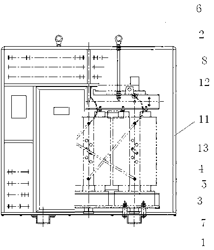
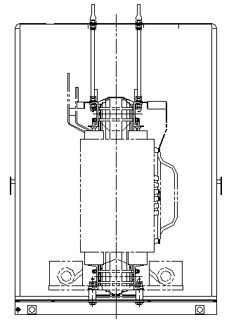
[0014] A dry-type transformer cover fixing structure, see figure 1 with figure 2 , the structure includes a trolley foot 1 arranged at the bottom of the transformer case 11 and a hanging screw 2 arranged on the upper clamp 12 of the transformer and protruding from the top of the transformer case 11. A base plate 3 is laid on the trolley foot, and a A support sleeve 5 with a bolt 4 is provided, and the position of the bolt corresponds to the position of the installation hole on the transformer lower clamp 13 ; a suspension ring 6 is provided on the top of the suspension screw 2 . There are two trolley feet, which are respectively arranged on the left and right sides of the transformer cover bottom. There are four hanging screw rods, and suspension rings are all arranged on the tops of the four hanging screw rods.

[0015] The specific assembly sequence is: place the trolley feet according to the installation gauge requirements, lay the bottom plate on the trolley feet, and p...


PUM


Abstract

The invention discloses a dry-type transformer housing fixing structure. The structure comprises small vehicle pins which are arranged at the bottom of a transformer housing, and lifting screw rods which are arranged on upper clamping components of a transformer and extend out of the top of the transformer housing, wherein a bottom plate is flatly paved on each small vehicle pin; support sleeves with bolts are arranged on each bottom plate; the position of each bolt is corresponding to that of an mounting hole in a lower clamping component of the transformer; and a lifting ring is arranged at the top of each lifting screw rod. According to the structure, the assembling efficiency of the transformer is improved greatly, so that the cost is lowered. Therefore, the structure disclosed by the invention is suitable for large-scale intensive production.

Description

[0001] technical field [0002] The invention belongs to the field of transformer manufacturing, and relates to the assembly of a dry-type transformer and a cover, in particular to a fixing structure for a dry-type transformer cover. Background technique [0003] The current installation structure between the dry-type transformer and the cover is to make a channel steel square frame at the bottom, and add a bottom plate in the middle of the frame. Connected by bolts, there is an openable door on the top of the casing. Open the top when transporting and hoisting, use a wire rope hook to hook the hanging plate on the transformer body for lifting, and close the top door after the transformer is in place. If long-distance wooden packaging transportation is required, a lifting seat made of several sleepers must be added to the bottom of the channel steel box, and the steel wire rope can only be used to lift from the bottom, which undoubtedly increases the difficulty of hoisting. ...

Claims


Application Information

Patent Timeline
Patent Type & Authority Applications(China)
IPC IPC(8): H01F41/00H01F27/02
Inventor 李云孙国平
Owner ZHENJIANG TIANLI TRANSFORMER
Why Eureka
Try Eureka