PCB flatbed magnetic device suitable for normal shock synchronous rectification
A PCB board and synchronous rectification technology, which is applied in the direction of electrical components, output power conversion devices, transformers/inductor coils/windings/connections, etc. Improvement and other issues to achieve the effect of reducing assembly difficulty, improving utilization rate, and meeting large current demand
- Summary
- Abstract
- Description
- Claims
- Application Information
AI Technical Summary
Problems solved by technology
Method used
Image

Examples
Embodiment 1
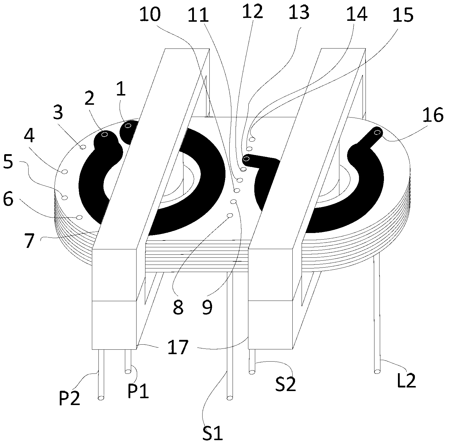
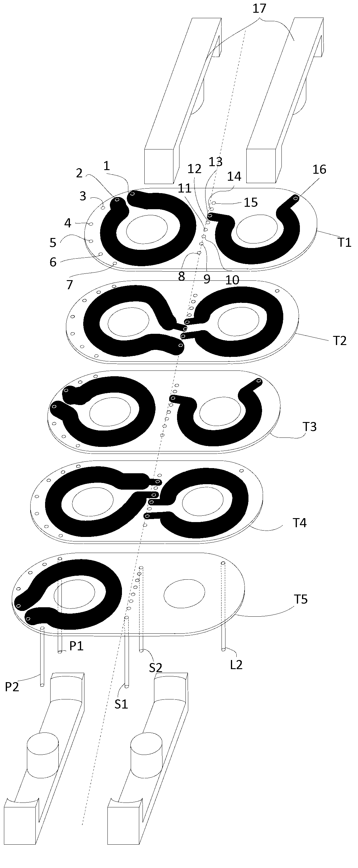
[0032] Such as image 3 , Figure 4 , Figure 5 As shown, in the example of the present invention, the entire magnetic device includes two pairs of EC-type magnetic cores, multiple double-layer PCBs with printed lines (5 pieces are used in this embodiment) as the primary and secondary windings of the transformer, and the inductor windings and 5 magnetics pins (including the transformer and inductor pins).
[0033] Among them, the magnetic core adopts flat EC-type high-frequency ferrite, which has the characteristics of low height and large effective area, especially the center shape of the magnetic core is arc-shaped, which can not only improve the utilization rate of PCB, but also reduce the magnetic flux leakage of the transformer . The double-layer PCB is the primary and secondary windings of the transformer and the winding of the inductor, and the copper foil on the PCB is the winding of the magnetic device. The top and bottom wires of each double-layer PCB represent t...
Embodiment 2
[0041] like Figure 4 , Figure 5 , Figure 6 As shown, in the example of the present invention, the entire magnetic device includes two pairs of EC-type magnetic cores, multiple double-layer PCBs with printed lines (5 pieces are used in this embodiment) as the primary and secondary windings of the transformer, and the inductor windings and 5 magnetics pins (including the transformer and inductor pins).
[0042] Among them, the magnetic core adopts flat EC-type high-frequency ferrite, which has the characteristics of low height and large effective area, especially the center shape of the magnetic core is arc-shaped, which can not only improve the utilization rate of PCB, but also reduce the magnetic flux leakage of the transformer . The double-layer PCB is the primary and secondary windings of the transformer and the winding of the inductor, and the copper foil on the PCB is the winding of the magnetic device. The top and bottom wires of each double-layer PCB represent two...
Embodiment 3
[0051] like Figure 5 , Figure 7 , Figure 8 As shown, in the example of the present invention, the entire magnetic device includes two pairs of EC cores, multiple double-layer PCBs with printed lines (7 pieces are used in this embodiment) as the primary and secondary windings of the transformer and the inductor winding and 5 magnetics pins (including the transformer and inductor pins).
[0052] Among them, the magnetic core adopts flat EC-type high-frequency ferrite, which has the characteristics of low height and large effective area, especially the center shape of the magnetic core is arc-shaped, which can not only improve the utilization rate of PCB, but also reduce the magnetic flux leakage of the transformer . The double-layer PCB is the primary and secondary windings of the transformer and the winding of the inductor, and the copper foil on the PCB is the winding of the magnetic device. The top and bottom wires of each double-layer PCB represent two turns of windin...
PUM
| Property | Measurement | Unit |
|---|---|---|
| Length | aaaaa | aaaaa |
| Width | aaaaa | aaaaa |
| Height | aaaaa | aaaaa |
Abstract
Description
Claims
Application Information
 - R&D Engineer
- R&D Manager
- IP Professional
- Industry Leading Data Capabilities
- Powerful AI technology
- Patent DNA Extraction
Browse by: Latest US Patents, China's latest patents, Technical Efficacy Thesaurus, Application Domain, Technology Topic.
© 2024 PatSnap. All rights reserved.Legal|Privacy policy|Modern Slavery Act Transparency Statement|Sitemap