
Viscosity measurement apparatus and method

A technology of viscosity and equipment, which is applied in the field of simultaneous measurement of solution viscosity, can solve problems such as the distribution map is not given, and achieve the effect of improving the measurement of viscosity

Active Publication Date: 2013-08-28
PARAYTEC
View PDF12 Cites 6 Cited by
  • Summary
  • Abstract
  • Description
  • Claims
  • Application Information

AI Technical Summary

Problems solved by technology

Moreover, PCT patent applications PCT / EP2009 / 053013 does not give advice on the distribution and viscosity of said species based on environmental detection

Method used


Image

  • Viscosity measurement apparatus and method
  • Viscosity measurement apparatus and method
  • Viscosity measurement apparatus and method

Examples


Embodiment Construction

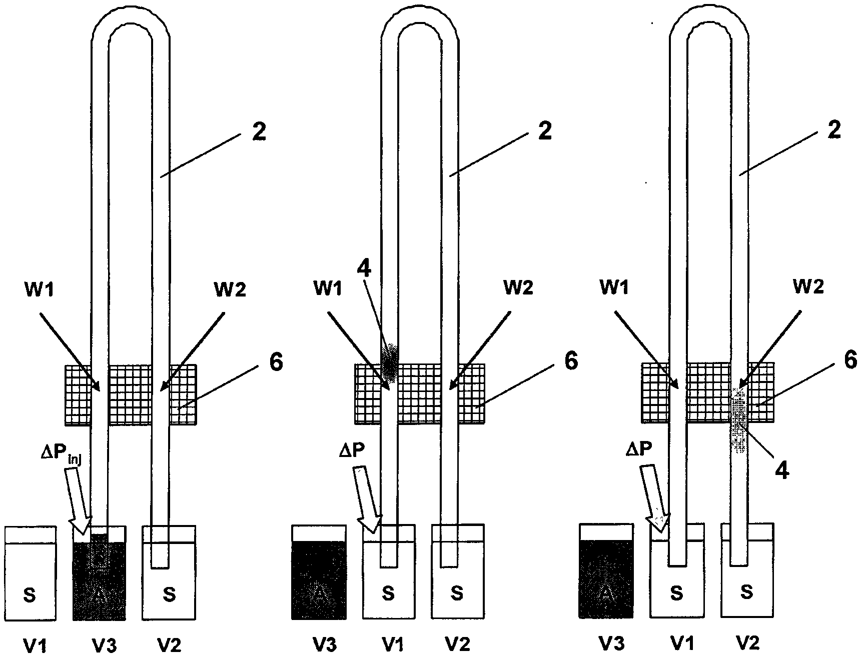
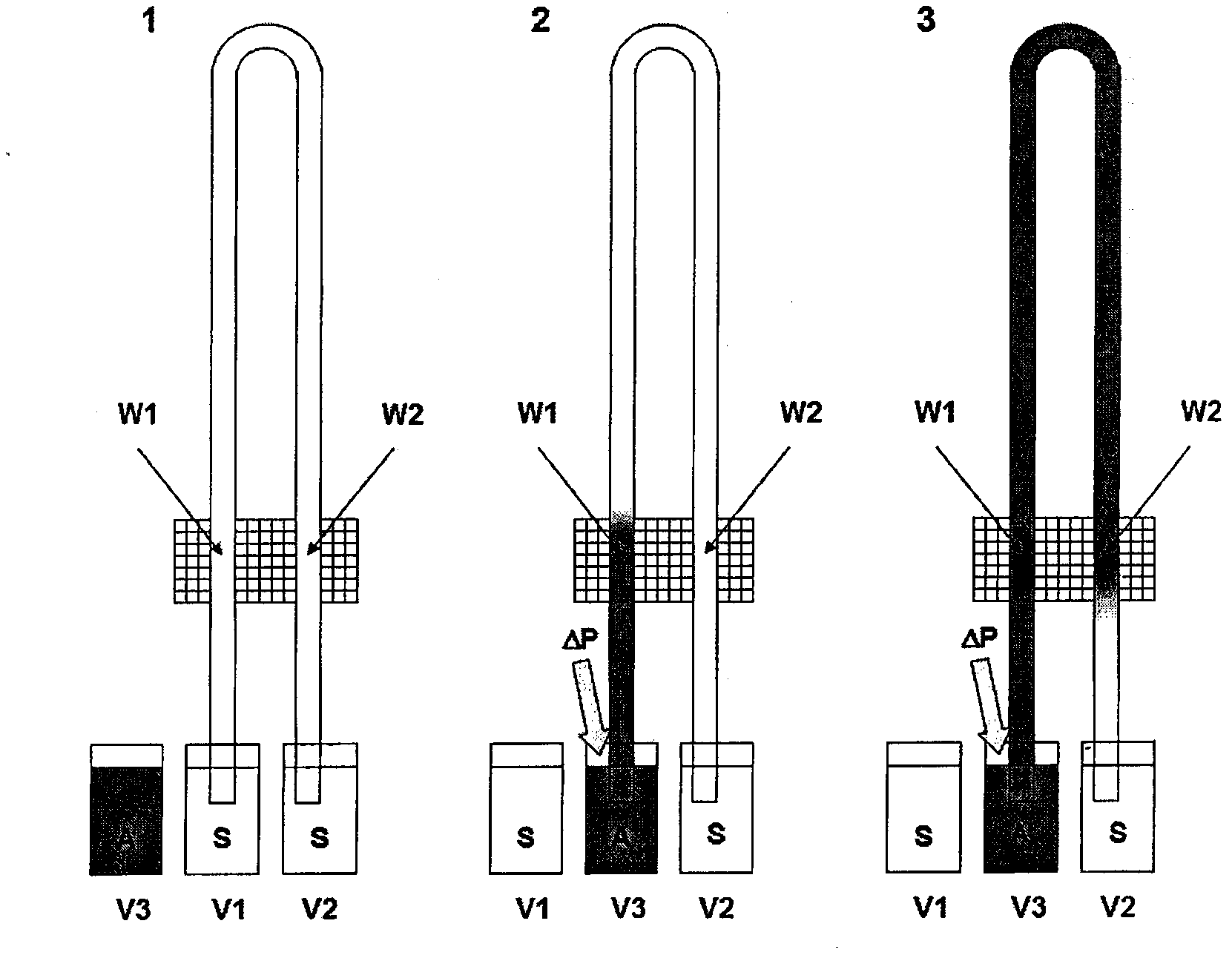
[0037] According to an embodiment of the present invention, there is provided a measurement apparatus and method which operates by driving a sample solution, solution A, through a capillary initially filled with carrier solution S at a constant pump pressure. Solution A can be injected as a pulse and followed by a continuous flow of solution S, or can be driven as a leading edge. The trend of the flow (SAS for pulse, SA for front) is imaged in two separate windows along the length of the capillary, for example using an assembly of the type described in US-7262847 including an area imager. Analyzing a series of frames as the sample pulse or sample front passes through each window can determine for each window the time to leave the window, the absorbance profile, and the change in the pulse or front. For spikes, the flow rate can also be determined. With knowledge of the length of the capillary and the position of the window, the specific viscosity of the sample solution can be...


PUM

PropertyMeasurementUnit
Wavelengthaaaaaaaaaa

Abstract

A method and apparatus for measuring the viscosity of a sample solution. A capillary (2) having first and second spaced apart detection windows (W1,W2) is filled with a carrier solution. A plug (4) or a continuous volume (4) of a sample solution is injected into the first end of the capillary (2) and pumped through the capillary (2) at a first pump pressure passing through the first and second detection windows (W1,W2). At least part of each detection window (W1,W2) is illuminated with a light source. Light from the light source passing through the carrier solution or the sample solution at each detector window (W1,W2) is detected using an array detector (6) comprising a two dimensional array of detector locations which generates an array detector output signal indicative of the profile of light absorbance of the sample solution plug (4) or flow front (4) passing through each detection window (W1,W2). From this the time difference between the time of detection of the sample solution plug (4) or flow front (4) at each detection window (W1,W2) is determined allowing the specific viscosity ?sp of the sample solution to be calculated taking into account a known time difference between the time of detection at each detection window (W1,W2) for a plug (4) or flow front (4) of a reference sample solution whose viscosity is approximately equal to the viscosity of the carrier solution when pumped at the first pump pressure.

Description

technical field [0001] The invention relates to a device and a method for measuring the relative viscosity and specific viscosity of a sample solution. Embodiments of the present invention provide a device for simultaneously measuring solution viscosity, solute concentration, diffusion coefficient, and size. Background technique [0002] Ultraviolet (UV) absorption is a key technique used in separation science to analyze species (molecules, ions, etc.) in a sample. A particular assembly employing this technique is disclosed in US Patent No. US-7262847 and European Patent No. EP-1530716-B1 belonging to the applicant. US Patent No. US-7262847 discloses an optical assembly comprising a light source, a plurality of sample containers in the form of capillaries and a detector. The capillary is arranged in the light path created between the light source and the detector in such a way that light rays can propagate through the capillary. The light source provides a parallel light ...

Claims


Application Information

Patent Timeline
IPC IPC(8): G01N11/04
CPCG01N11/04G01N21/33G01N11/06
Inventor 戴维·古道尔
Owner PARAYTEC
Features
  • Generate Ideas
  • Intellectual Property
  • Life Sciences
  • Materials
  • Tech Scout
  • Unparalleled Data Quality
  • Higher Quality Content
  • 60% Fewer Hallucinations
Learn More