Five-freedom degree magnetic levitation guide rail with novel electromagnet distribution

A technology of electromagnets and degrees of freedom, applied in the directions of bearings, shafts and bearings, mechanical equipment, etc., can solve the problem of mutual coupling of magnetic fields, and achieve the effect of solving mutual coupling of magnetic fields and improving control accuracy

Active Publication Date: 2013-09-04
HARBIN INST OF TECH
View PDF5 Cites 18 Cited by
  • Summary
  • Abstract
  • Description
  • Claims
  • Application Information

AI Technical Summary

Problems solved by technology

[0007] The present invention is to solve the problem of magnetic field mutual coupling between adjacent electromagnets in the ma...

Method used


Image

  • Five-freedom degree magnetic levitation guide rail with novel electromagnet distribution
  • Five-freedom degree magnetic levitation guide rail with novel electromagnet distribution
  • Five-freedom degree magnetic levitation guide rail with novel electromagnet distribution

Examples


specific Embodiment approach 1

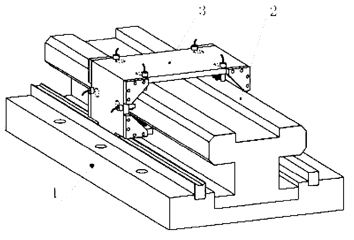
[0026] Specific implementation mode one: combine figure 1 , figure 2 , image 3 and Figure 4 This embodiment will be described. The new five-degree-of-freedom maglev guide rail with electromagnet distribution described in this embodiment includes a base 1, a guide rail 2 fixed on the base 1, and a suspension platform 3 sleeved on the outside of the guide rail 2, and is set on the suspension platform 3. 12 pieces of electromagnets, and the air gap detection displacement sensor group arranged on the suspension platform 3 for detecting the motion state of the suspension platform 3 in each direction; the suspension force of the 12 pieces of electromagnets and the air gap detection displacement of the suspension platform 3 Under the feedback of the sensor group, it is stably suspended on the guide rail 2 (in the form of wrapping the guide rail 2).

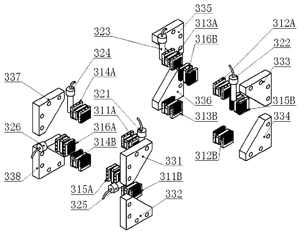
[0027] The 12 electromagnets providing five-degree-of-freedom suspension include: the first electromagnet 311A ​​and the second ...

specific Embodiment approach 2

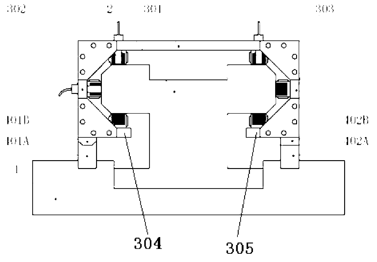
[0029] Specific implementation mode two: combination image 3 and Figure 4 This embodiment will be described. The suspended platform 3 includes an upper support plate 301 connected by corresponding connecting plates 331, 332, 333, 334, 335, 336, 337, 338, a left support plate 302 fixed on the left end of the upper support plate 301, a fixed support plate The right side support plate 303 at the right end of the upper support plate 301, the left side lower support plate 304 that is located below the upper support plate 301 and fixed on the free end of the left support plate 302, and the lower support plate 304 that is located under the upper support plate 301 and is fixed on the left side support plate 301. The right lower support plate 305 at the free end of the right support plate 303 is perpendicular to each other between two adjacent support plates.

[0030] The first electromagnet 311A, the third electromagnet 312A, the fifth electromagnet 313A and the seventh electromagne...

specific Embodiment approach 3

[0032] Specific implementation mode three: combination Figure 5 This embodiment will be described. Figure 5 It is the structural diagram of each electromagnet described in the present invention, all electromagnets all adopt U-shaped structure, and the iron core adopts silicon steel sheet 341 to superimpose and form, close to cooling pipe 344 on both sides of copper winding 343, fixing piece 342 will electromagnet It is fixed on each support plate of the suspension platform 33.


PUM


Abstract

The invention discloses a five-freedom degree magnetic levitation guide rail with novel electromagnet distribution, which comprises a guide rail, a levitation platform, a plurality of electromagnets equipped on the levitation platform and a air gap detection displacement sensor group for detecting motion state on each direction of the levitation platform. A plurality of electromagnets are oppositely arranged on the levitation platform in pair, and excitation of each group of electromagnet pair is set with a differential control mode for providing stable levitation force and guidance force. The plane where the work magnetic circuit of each electromagnet is located is parallel to the operation direction of the levitation platform; the winding current directions of the three electromagnets located at one corner of the levitation platform are identical. The electromagnetic attraction produced by the electromagnet according to the invention can realize five-freedom degree levitation of the levitation platform, thereby solving the magnetic field coupling problem between electromagnets, and the levitation platform has the advantages of contactless, non-lubrication, long stroke, high precision, high speed and adjustable static state rigidity, etc., and the product is suitable for the linear feeding equipment such as high-grade numerical control machine tool and mask aligner or the like which need ultra-clean, high precision and other performances.

Description

technical field [0001] The invention belongs to the field of precision machining, and in particular relates to a novel five-degree-of-freedom maglev guide rail distributed with electromagnets. Background technique [0002] In the field of modern manufacturing, the requirements for precision machining equipment are gradually increasing, especially for high-speed, high-precision linear feed platforms, such as high-end CNC machine tools and lithography machines for IC manufacturing equipment. The traditional linear feed platform uses mechanical support technology, such as sliding guide rails and rolling guide rails. These mechanical guide rails have problems such as friction loss, metal dust, lubrication and maintenance, and are not suitable for some high-speed, high-precision and ultra-clean environments. occasion. [0003] In recent years, the air-floating support technology has been gradually applied to the linear feed platform to solve the problems of mechanical friction a...

Claims


Application Information

Patent Timeline
IPC IPC(8): F16C32/04
CPCF16C32/0472
Inventor 李立毅王明义曹继伟刘家曦张成明
Owner HARBIN INST OF TECH
Why Eureka
Try Eureka