Single concave cavity trapped vortex combustor

A combustor and cavity technology, applied in the field of new concept aviation gas turbine combustion, can solve the problems of stability and combustion efficiency limitation of trapped vortex combustor, complex fuel system, etc., to improve combustion efficiency and ignition performance, simple fuel system, The effect of reducing the weight of the combustion chamber

Inactive Publication Date: 2015-10-28
NANJING UNIV OF AERONAUTICS & ASTRONAUTICS
View PDF4 Cites 2 Cited by
  • Summary
  • Abstract
  • Description
  • Claims
  • Application Information

AI Technical Summary

Problems solved by technology

[0005] The stability and combustion efficiency of the trapped vortex combustor are limited by the size of the cavity, and the fuel system is relatively complicated

Method used


Image

  • Single concave cavity trapped vortex combustor
  • Single concave cavity trapped vortex combustor
  • Single concave cavity trapped vortex combustor

Examples


Embodiment Construction

[0040] The present invention will be described in detail below in conjunction with the accompanying drawings and specific embodiments.

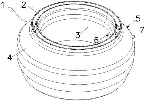
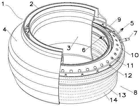
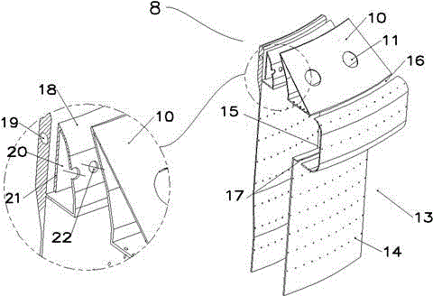
[0041] Please refer to Figure 1 to Figure 5 As shown, the single-cavity vortex combustion chamber of the present invention is mainly composed of a diffuser 2, a combustion chamber casing 3 and an outer casing 4, a flame cylinder 8 with a single-cavity structure, a flow guiding device 10, a pre-evaporation device 18, etc. composition. The single-cavity vortex combustion chamber has a full ring structure, using the vortex formed by the concave cavity 15 in the flame tube to stabilize the flame, relying on the cross-flame support plate 23 to transmit the flame from the concave cavity 15 to the main flow 25, combined with RQL combustion technology and LPP staged combustion technology achieves high efficiency and low emissions.

[0042] A diffuser 2 is arranged at the inlet of the combustion chamber, and its main function is to reduce the air v...


PUM


Abstract

A single-cavity trapped vortex combustor comprises a pressure expander, an inner cartridge receiver, an outer cartridge receiver, a flame tube, a flow guide device, a pre-evaporation device, an oil supply system and a high-energy spark plug, wherein airflow at an inlet of the combustor enters the combustor through the pressure expander, the flame tube is of a single-cavity structure, the inner cartridge receiver, the outer cartridge receiver and the flame tube form an inner duct and an outer duct of the combustor, the flow guide device separates the main flow from the air of the outer duct, air is decelerated and pressurized through the pressure expander, is divided into four paths through the flow guide device and the pre-evaporation device, and respectively enters the main flow, the pre-evaporation device, the inner duct and the outer duct, and the high-energy spark plug is arranged at the bottom of the cavity. The combustion area of the single-cavity trapped vortex combustor is divided into a trapped vortex area and a main combustion area, and the single-cavity trapped vortex combustor further comprises a flame joint supporting plate which transmits flames from a cavity to the main flow.

Description

Technical field: [0001] The invention relates to a single-cavity vortex combustion chamber, which is mainly used as the main combustion chamber of an aero-engine, and belongs to the technical field of new-concept aero-gas turbine combustion. Background technique: [0002] With the further development of aero-engine technology, the thrust-to-weight ratio continues to increase, the inlet temperature of the combustion chamber increases, the oil-gas ratio and temperature rise of the combustion chamber increase, and the requirements for the performance of the combustion chamber gradually increase, but at the same time, the weight of the combustion chamber is limited. Further increase, therefore, the development of the high-fuel ratio combustion chamber is facing many technical challenges: 1. Stable operation in a wider range, mainly to solve the combustion stability under low power state and the invisible exhaust leakage under high power state; Smoke combustion; 2. Under the cond...

Claims


Application Information

Patent Timeline
Patent Type & Authority Patents(China)
IPC IPC(8): F23R3/00F23R3/28
Inventor 何小民吴泽俊金义蒋波郝艳娜丁国玉朱志新赵自强方杰
Owner NANJING UNIV OF AERONAUTICS & ASTRONAUTICS
Why Eureka
Try Eureka