Pulverized coal preheating burner and pulverized coal preheating combustion method

A burner and pulverized coal technology, applied in the field of combustion, can solve problems such as difficult application, difficult to provide pulverized coal, and increase system complexity, and achieve low NOX emission combustion and simple structure

Active Publication Date: 2018-01-30
INST OF ENGINEERING THERMOPHYSICS - CHINESE ACAD OF SCI
View PDF6 Cites 0 Cited by
  • Summary
  • Abstract
  • Description
  • Claims
  • Application Information

AI Technical Summary

Problems solved by technology

CN102032564A discloses a method of using plasma or a small oil gun in front of the combustion device to continuously preheat the pulverized coal, and then send the preheated pulverized coal into the combustion chamber for combustion; this method requires an external heat source to continuously heat the pulverized coal, which increases the system's Complexity
CN1082164A discloses a fluidized bed pulverized coal pre-combustion heating and combustion device. A small fluidized bed pulverized coal pre-combustion heating chamber is arranged outside the pulverized coal primary air nozzle, in order to use difficult-to-combustible coal and solve the problem of low temperature in pulverized coal boilers. Combustion support is usually required under load; since the pulverized coal added to the pre-combustion heating chamber will be directly transported upwards to the outlet of the combustion chamber by the fluidization wind, a hot dense phase area cannot be formed at the bottom of the heating chamber, so it is difficult to provide high-temperature pulverized coal
CN101158468A discloses a high-temperature preheating method for pulverized coal. The pulverized coal is fed from the middle and lower part of the circulating fluidized bed combustion chamber, air is introduced from the bottom, and the pulverized coal is partially burned to release heat to preheat the pulverized coal to above 800°C; Since the powder delivery system of pulverized coal power plant boilers usually uses primary air to carry coal powder to form a mixture of air powder and spray it into the boiler combustion device, this method is difficult to directly apply to existing power plant boilers

Method used


Image

  • Pulverized coal preheating burner and pulverized coal preheating combustion method
  • Pulverized coal preheating burner and pulverized coal preheating combustion method
  • Pulverized coal preheating burner and pulverized coal preheating combustion method

Examples


Embodiment 1

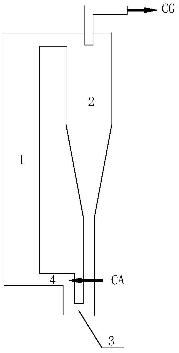
[0040] Such as figure 1 The pulverized coal preheating combustion device shown includes a preheating combustion chamber 1, a gas-solid separator 2, and a U-shaped feeder 3 connected in sequence. The preheating combustion chamber 1 is a vertical cylinder, and the bottom is connected through a horizontal The pipeline 4 is connected to the feeder 3, and the top is connected to the gas-solid separator 2; the top outlet of the ascending section of the feeder 3 is provided with an air-powder mixture inlet, and the air-powder mixture CA is introduced. The air-powder mixture is coal powder with a particle size not exceeding 500 μm carried by the pulverized coal exhaust gas from the pulverized coal boiler pulverization system. The ratio of coal grinding exhaust gas to coal powder is equivalent to the amount of oxygen / theoretical oxygen amount of fuel combustion = 0.1~0.2. The gas outlet of the gas-solid separator, that is, the outlet of the preheating combustion device, is connected w...

Embodiment 2

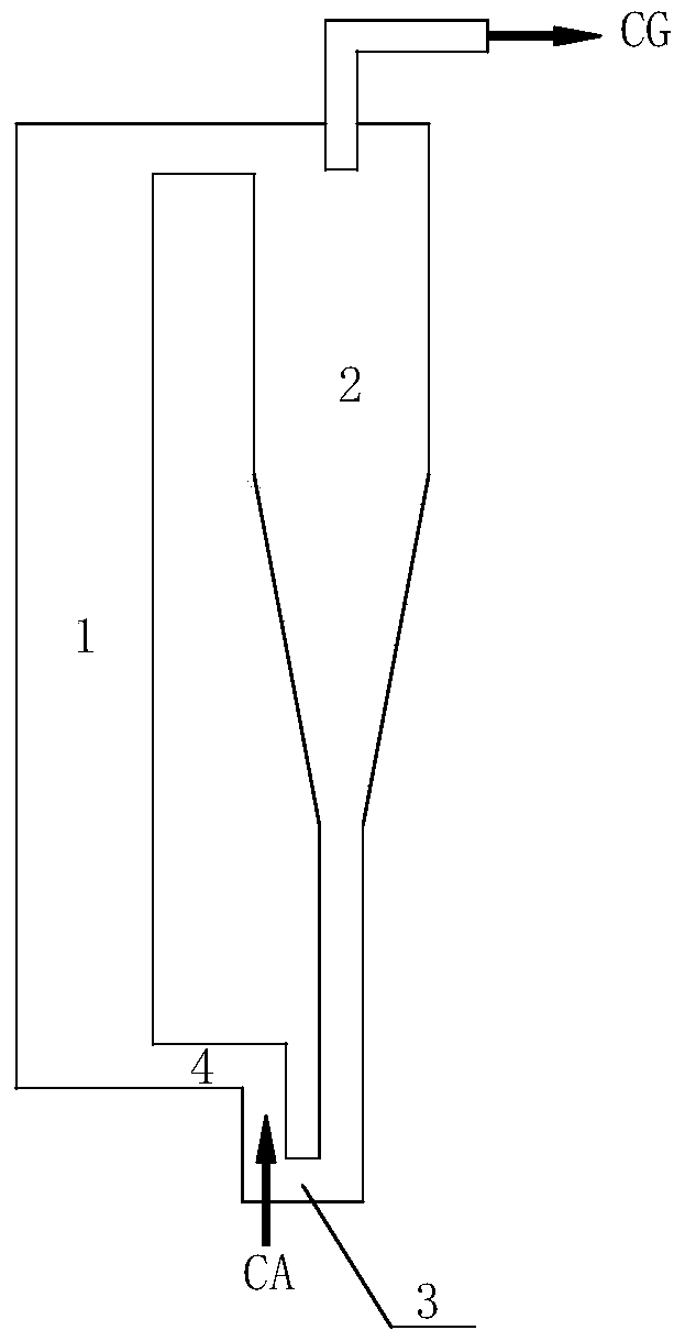
[0042] Such as figure 2 The difference between the pulverized coal preheating combustion device shown in Example 1 is that the air powder mixture inlet is arranged at the upper middle part of the rising section of the U-shaped feeder 3 .

Embodiment 3

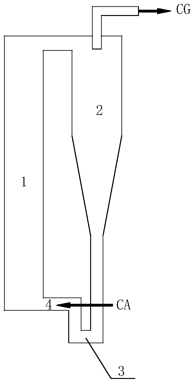
[0044] Such as image 3 The pulverized coal preheating combustion device shown differs from Embodiment 1 in that the air powder mixture inlet is arranged on the horizontal connecting pipe 4 connected to the bottom of the preheating combustion chamber 1 and the rising section of the U-shaped feeder 3 .


PUM


Abstract

The invention relates to a pulverized coal preheating burner, comprising: a preheating combustion chamber connected in sequence, a gas-solid separator and a U-shaped feeder, the U-shaped feeder includes a descending section and an ascending section, and the bottom of the preheating combustion chamber It is directly connected to the outlet of the ascending section of the U-shaped feeder or connected through a connecting pipe; and the air powder mixture inlet is arranged on the ascending section of the U-shaped feeder or the connecting pipe or the bottom of the preheating combustion chamber, and the air powder mixture added The air-powder mixture inlet is configured to move the air-powder mixture towards the preheated combustion chamber. The invention also relates to a pulverized coal preheating combustion method.

Description

technical field [0001] The invention relates to the technical field of combustion, in particular to a pulverized coal preheating burner of a pulverized coal boiler and a preheating combustion method thereof. technical background [0002] With the increasing shortage of coal resources in our country, more and more anthracite is used for direct power generation. However, due to the low volatile content and high fixed carbon content of anthracite, it is difficult to ignite, and its combustion stability and burnout are poor. Other fuels with a volatile content of less than 10%, such as semi-coke and gasified fine powder ash, also have the above-mentioned problems, and cannot be effectively utilized by traditional combustion equipment. [0003] In the prior art, such fuels are burned and utilized mainly through preheating and then burning. CN102032564A discloses a method of using plasma or a small oil gun in front of the combustion device to continuously preheat the pulverized ...

Claims


Application Information

Patent Timeline
Patent Type & Authority Patents(China)
IPC IPC(8): F23C10/10
Inventor 吕清刚欧阳子区朱建国高鸣那永洁
Owner INST OF ENGINEERING THERMOPHYSICS - CHINESE ACAD OF SCI
Why Eureka
Try Eureka