Feedforward type variable optical delay line

A delay line and feed-in technology, applied in the field of optical communication, can solve the problems of signal crosstalk, limited extinction ratio, affecting the quality of the output optical signal, etc., and achieve the effect of improving the delay bandwidth product and suppressing the crosstalk.

Inactive Publication Date: 2013-09-04
SHANGHAI JIAO TONG UNIV
View PDF3 Cites 19 Cited by
  • Summary
  • Abstract
  • Description
  • Claims
  • Application Information

AI Technical Summary

Problems solved by technology

Due to process errors, the extinction ratio of the two output ports of the optical switch based on the Mach-Zehnder interferometer is limited, and the optical signal cannot be completely switched to one port output,

Method used


Image

  • Feedforward type variable optical delay line
  • Feedforward type variable optical delay line
  • Feedforward type variable optical delay line

Examples


Embodiment

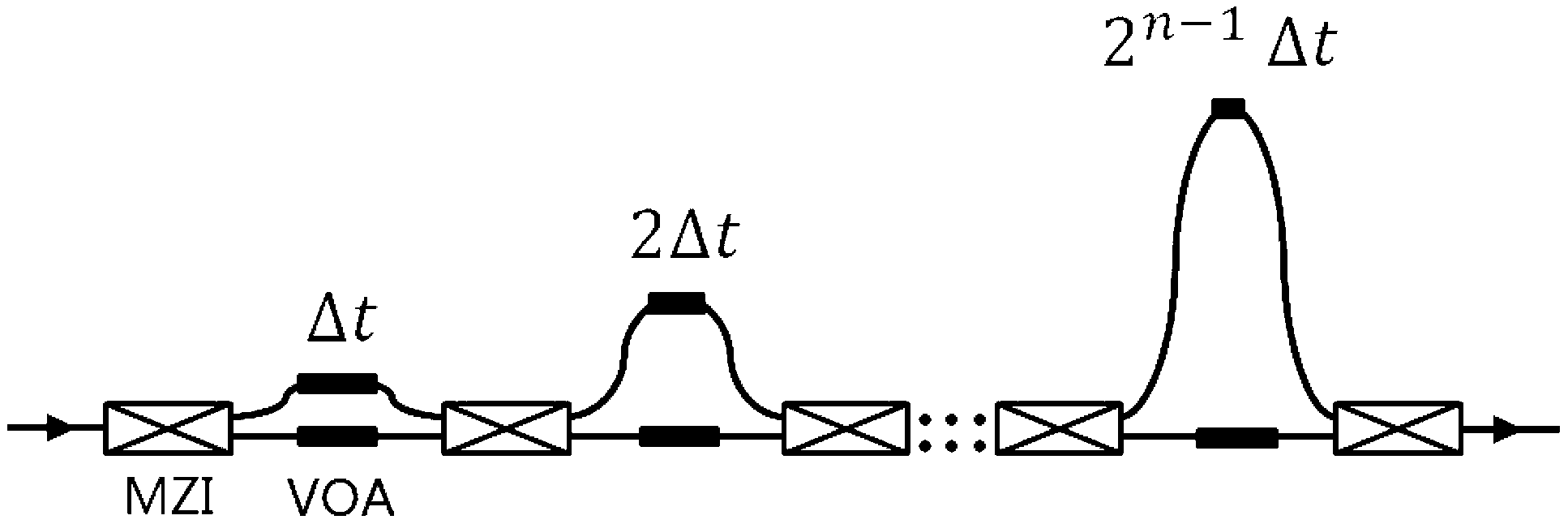
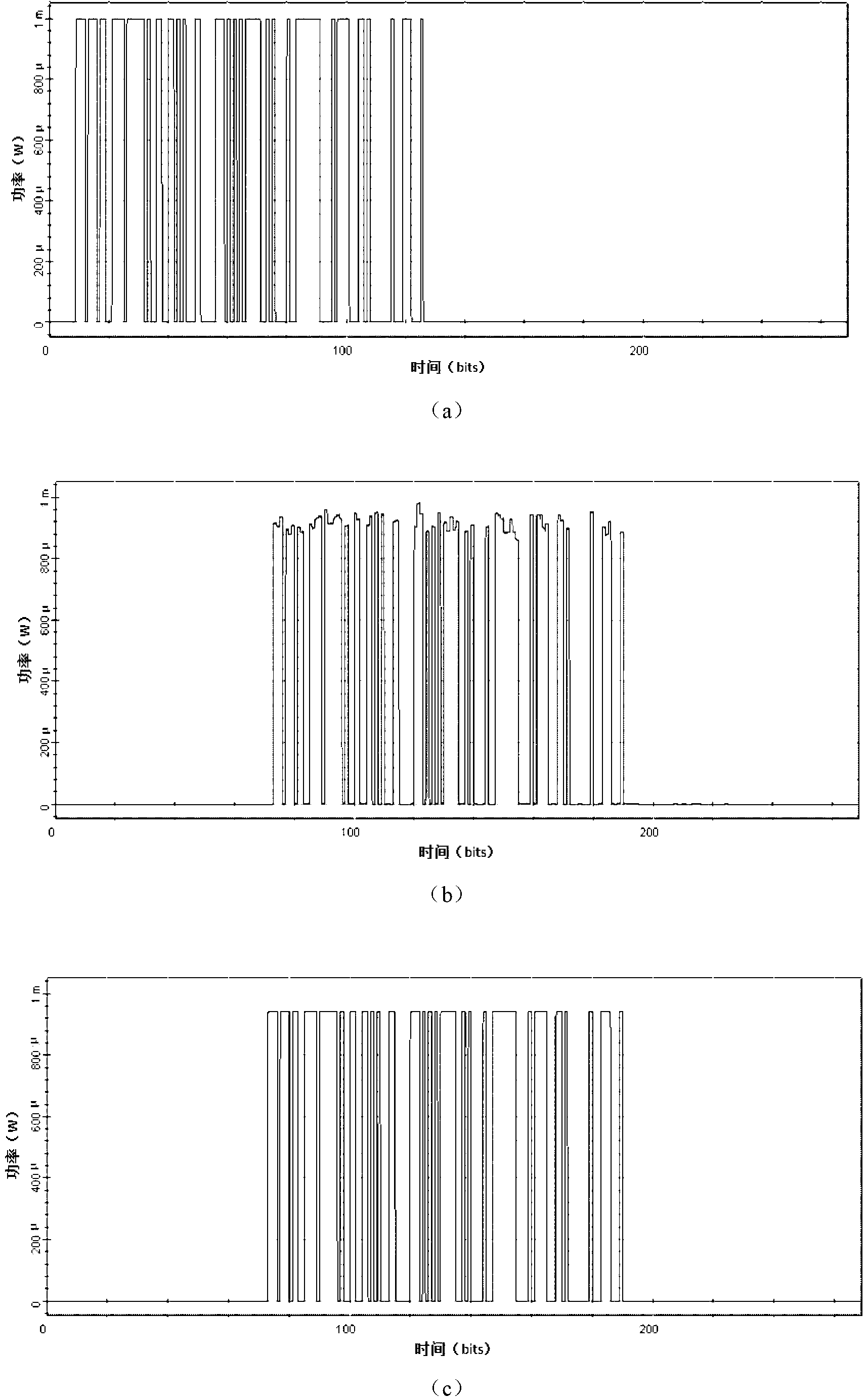
[0030] In this embodiment, there are 8 MZIs in total, the MZIs are single-arm modulation, and the extinction ratio is 21dB. VOA is added to the waveguide between every two MZIs, that is, there are 14 VOAs in total. The VOA is adjusted by p-i-n electrodes, and the system reference delay The quantity is 25ps, and the input is an OOK signal with a central wavelength of 1550nm at 40Gb / s. When the two MZI optical switches of the first stage and the eighth stage are in the BAR state, the input and output of the optical delay line are connected to the long waveguide. Now delay the OOK signal by 1600ps, which corresponds to 64 bits of baseband, according to 64=1×2 6 +0×2 5 +0×2 4 +0×2 3 +0×2 2 +0×2 1 +0×2 0 , the weight 0 or 1 means that when the optical signal passes through a certain level of MZI, it chooses to propagate through the short waveguide or long waveguide to obtain the corresponding delay, so the 2nd, 3rd, 4th, 5th, 6th, and 8th MZIs need to be placed in the BAR sta...


PUM


Abstract

A feedforward type variable optical delay line comprises a plurality of Mach-Zehnder interferometers which are connected in series sequentially. One output end of the Mach-Zehnder interferometer at the present level is connected with an input end of the Maxh-Zehnder interferometer at a next level through a long waveguide, the other output end of the Mach-Zehnder interferometer in the present level is connected with the other input end of the Mach-Zehnder interferometer in the next level through a short waveguide, and a pair of variable optical attenuators are further arranged on the waveguides between each two Mach-Zehnder interferometers. In the feedforward type variable optical delay line, optical signals do not pass through a resonance structure in waveguide transmission, through switching of transmission paths of the optical signals, continuous adjustment with a certain standard delay amount as a delay unit is realized, at the same time, the variable optical attenuators are used for restraining crosstalk on the waveguides, and therefore delay bandwidth product is improved to the largest degree.

Description

technical field [0001] The present invention relates to an integrated device in the field of optical communication technology, specifically a feed-forward adjustable optical delay line based on a 2×2 optical switch, a waveguide delay line, and an adjustable optical attenuator, which realizes a time delay based on a certain reference The large-scale delay can be adjusted continuously in the unit of quantity, and the crosstalk caused by the bypass signal interference can be suppressed to the greatest extent, and the performance of the delayed optical signal can be improved. Background technique [0002] Integratable optical buffer is a key component in next-generation high-speed optical communication systems. It is a process that can be used to realize all-optical processing in optical packet switching networks to replace the optical-electrical-optical conversion required by optical network packets at routing nodes. After searching the existing literature, it is found that in ...

Claims


Application Information

Patent Timeline
IPC IPC(8): G02B6/35G02B6/26
Inventor 陈治龙周林杰谢静雅邹志陆梁军孙晓萌陈建平
Owner SHANGHAI JIAO TONG UNIV
Why Eureka
Try Eureka