
Energy management tree and energy management method

An energy management and energy technology, applied in the field of energy management, can solve problems such as inability to solve energy management problems, data collection that does not conform to the visual energy management system, and inability to realize the visual energy saving effect of the energy management system. The effect of investment bottlenecks

Inactive Publication Date: 2013-09-04
天津至勤科技发展有限公司
View PDF2 Cites 0 Cited by
  • Summary
  • Abstract
  • Description
  • Claims
  • Application Information

AI Technical Summary

Problems solved by technology

At present, due to the large one-time investment in the implementation of the visual energy management system, especially the high proportion of investment in the field instruments of the enterprise, the implementation of the energy management system is invested in stages, and most of the field instruments in the enterprise do not have communication capabilities. Functional sensing equipment does not meet the data acquisition requirements of the visualized energy management system, resulting in long project cycles and slow construction progress, which cannot realize the visualization of the energy management system and the expected energy-saving effect
Shanghai Baosight Software Co., Ltd. discloses an energy management system for metallurgical enterprises. The invention patent publication number is CN101256642A. Shenzhen Haiyida Electronics Co., Ltd. discloses an energy management method, system and energy dispatching management center. The invention patent application The publication number is CN101976390A, these two patents cannot solve the energy management problems existing in the above-mentioned industrial sites

Method used


Image

  • Energy management tree and energy management method

Examples


Embodiment Construction

[0008] In order to make the purpose, method and advantages of the present invention clearer, the present invention will be further described in detail below with reference to the accompanying drawings and specific embodiments. It should be understood that the specific embodiments described herein are only used to explain the present invention, but not to limit the present invention.

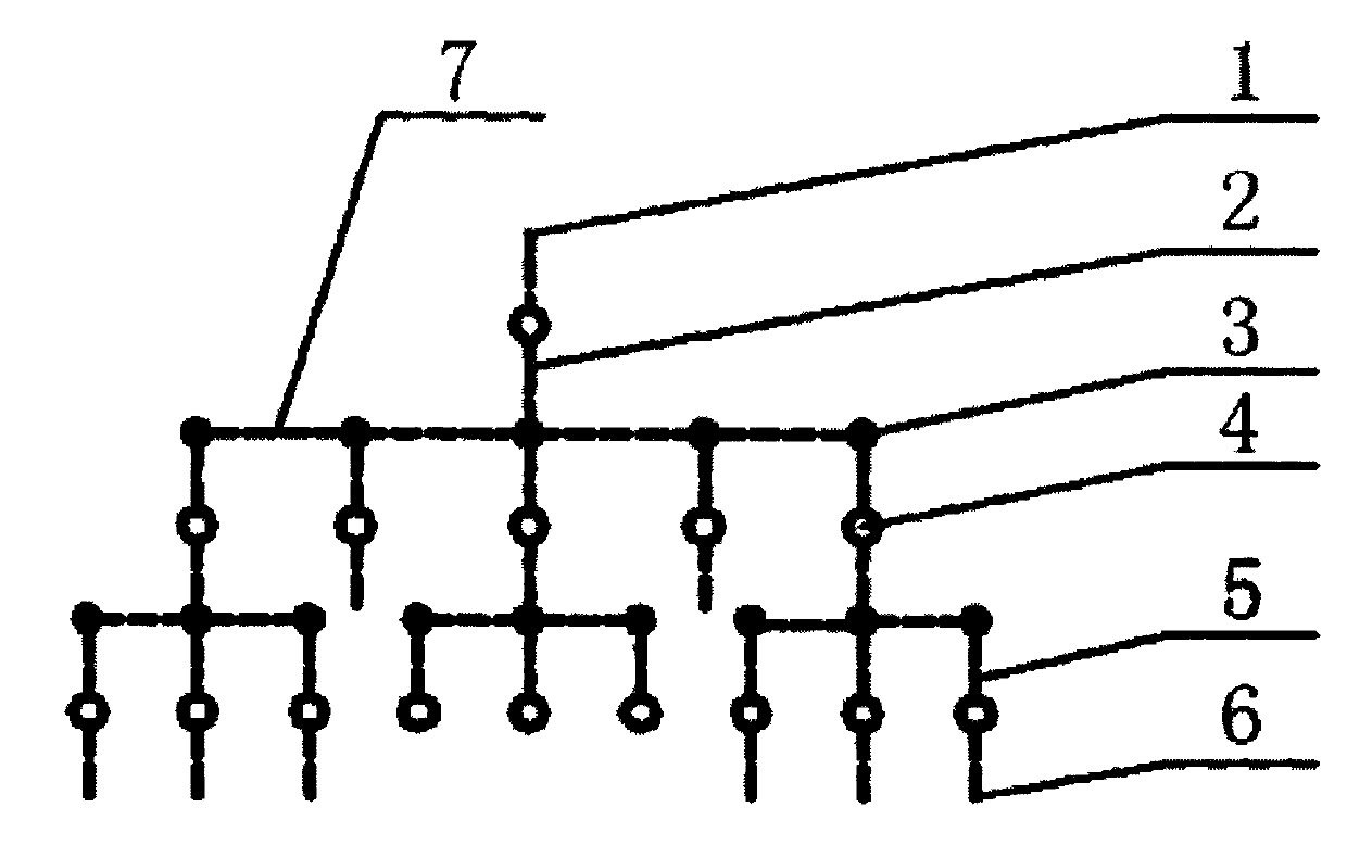
[0009] figure 1 As shown in the energy management tree, the energy management tree consists of an inlet energy virtual pipeline 2, a distributed intermediate energy virtual pipeline 7, a distributed outlet energy virtual pipeline 5, a distributed energy metering point 4 and a distributed connection point 3. One end of the inlet energy virtual pipe 2 is the energy medium inlet 1, the other end is connected to the distributed intermediate energy virtual pipe 7 through the distributed connection point 3, one end of the distributed energy virtual pipe 5 is the distributed energy medium outlet 6, and ...


PUM


Abstract

The invention discloses an energy management tree and an energy management method. The energy management tree comprises an inlet energy virtual pipeline (2), distributed middle energy virtual pipelines (7), distributed outlet energy virtual pipelines (5), distributed energy metering points (4) and distributed connecting points (3), and the energy management tree is formed by connecting the inlet energy virtual pipeline (2), the distributed middle energy virtual pipelines (7) and the distributed outlet energy virtual pipelines (5) in series or in parallel. The energy management method based on the energy management tree comprises the steps that sensing equipment is installed on the distributed energy metering points (4), and an energy state table for the energy metering points is built to conduct fuzzy metering, wherein the sensing equipment without a communication function is installed on the energy metering points. Therefore, the problem that a plurality of sensing equipment without the communication function are required to be replaced when an enterprise operates a visual energy management system is solved, investment cost is saved, the energy informatization process is accelerated, and a great amount of energy is saved for the enterprise through the energy management system.

Description

technical field [0001] The invention belongs to the field of energy management, and in particular relates to an energy management tree and an energy management method. Background technique [0002] At present, energy management mainly includes contract energy management and visual energy management system. Contract energy management is based on the visual energy management system. Through management energy saving, behavioral energy saving, and structural energy saving, we can find technical energy saving points, and target energy saving through contract energy management. equipment modification. At present, due to the large one-time investment in the implementation of the visual energy management system, especially the high proportion of the investment in the field instruments of the enterprise, the implementation of the energy management system is a phased investment, and most of the enterprise field instruments do not have communication. The functional sensing equipment d...

Claims


Application Information

Patent Timeline
Patent Type & Authority Applications(China)
IPC IPC(8): G06Q10/06G06Q50/00
Inventor 陈志强
Owner 天津至勤科技发展有限公司
Learn More