electronic card connector

A technology of electronic cards and connectors, which is applied in the direction of connection, parts and circuits of connection devices, etc., which can solve problems affecting the use of card connectors, wear and tear of push rods, etc., and achieve simple structure, avoid wear, and good stability Effect

Active Publication Date: 2015-09-09
KUNSHAN JIAHUA ELECTRONICS
View PDF4 Cites 0 Cited by
  • Summary
  • Abstract
  • Description
  • Claims
  • Application Information

AI Technical Summary

Problems solved by technology

[0003] However, in the prior art, after the card connector is pulled out from the tray, since there is no part to prevent the movement of the push rod, when the tray is pulled out, the push rod will move freely back and forth along the insulating body, thus easily causing the push rod to move. wear and tear, and even breakage, which will affect the use of the card connector

Method used


Image

  • electronic card connector
  • electronic card connector
  • electronic card connector

Examples


Embodiment Construction

[0024] The present invention will be described in detail below in conjunction with various embodiments shown in the drawings. However, these embodiments do not limit the present invention, and any structural, method, or functional changes made by those skilled in the art according to these embodiments are included in the protection scope of the present invention.

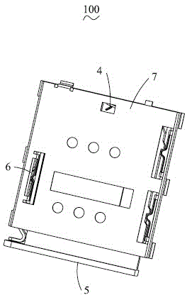
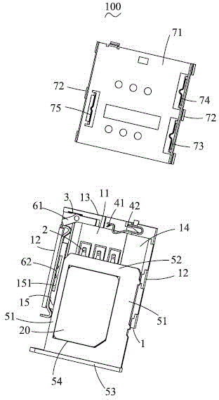
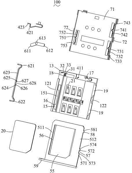
[0025] Please refer to Figure 1 to Figure 7 , shows a preferred embodiment of the electronic card connector 100 of the present invention. The electronic card connector 100 includes an insulating body 1, a number of conductive terminals 2 fixed on the insulating body 1, a pair of switch terminals 4 fixed on one side of the insulating body 1, selectively inserted into the insulating body 1 to accept the first type The first tray 5 of the electronic card 20 or the second tray 8 to accept the second type of electronic card 30, the withdrawal mechanism 6 for withdrawing the first tray 5 or the second tray 8 from the in...


PUM


Abstract

The invention relates to an electronic-card connector, which comprises an insulation body, a conductive terminal, a tray, a shielding shell and a quitting mechanism, wherein the insulation body has a containing space, and the conductive terminal is fixedly arranged on the insulation body; the tray is inserted into the containing space to bear one electronic card, and the shielding shell is used for shielding the insulation body; and the quitting mechanism is fixedly arranged on the insulation body to enable the tray to quit the containing space. The tray comprises a side rod and a lock catch groove, the side rod extends along the inserting direction of the electronic-card connector, and the lock catch groove is formed at the outer side of the side rod. The quitting mechanism comprises a push rod which is arranged at one side of the insulation body. The push rod comprises a rod body and a convex piece, the rod body extends along the inserting direction of the electronic-card connector, and the convex piece outwards extends from the rod body. The shielding shell comprises a top wall, a limiting arm and a lock catch arm, the top wall shields above the insulation body, and the limiting arm is formed in a mode of downwards extending from the top wall. The limiting arm is provided with a stopping part, and the stopping part extends to the push rod and blocks in front of the convex piece when the tray is in a quitting state. The lock catch arm is provided with a lock catch part, and the lock catch part extends into the containing space in a convex way and is locked in the lock catch groove when the tray is in an inserted state.

Description

technical field [0001] The invention relates to an electronic card connector, in particular to an electronic card connector with simple structure. Background technique [0002] As a data transmission medium of an electronic card for receiving and accessing data, the electronic card connector has been widely used in various fields, such as computers, digital cameras, mobile phones and so on. Electronic card connectors usually include an insulating body, a number of conductive terminals fixed in the insulating body to connect the electronic card with power supply, and a shielding shell covering the insulating body to shield external interference; The accommodating space, the conductive terminal is provided with a contact portion protruding into the accommodating space. In order to facilitate the user to install the electronic card, a tray is provided in the receiving space, and the tray is provided with an opening through which the contact portion of the conductive terminal p...

Claims


Application Information

Patent Timeline
Patent Type & Authority Patents(China)
IPC IPC(8): H01R13/639H01R13/514H01R13/46H01R13/629H01R12/71
Inventor 张佳华
Owner KUNSHAN JIAHUA ELECTRONICS
Why Eureka
Try Eureka